GL16 Operating Principles
5-13
Touchless Temperature Sensors and
UV Flame Scanners
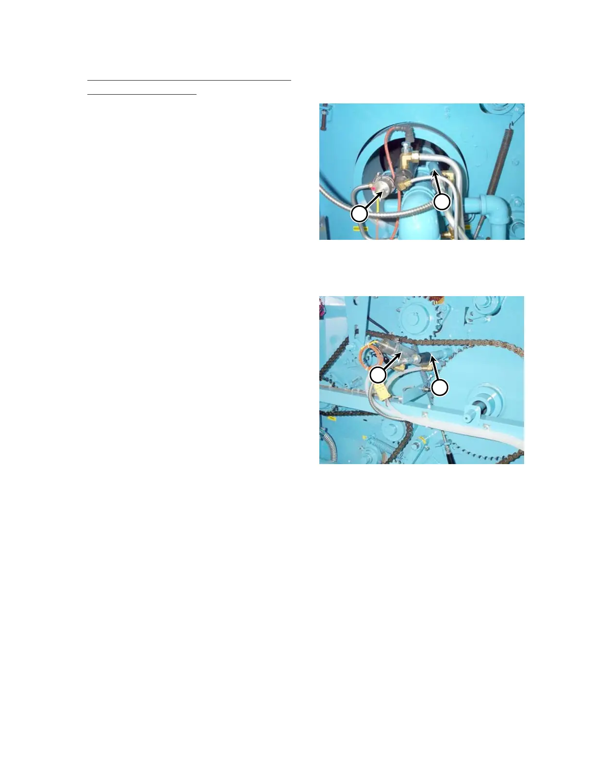
The unit is equipped with two touchless
temperature sensors, one inside each end frame.
They monitor the temperature of the ironing
cylinder. The touchless temperature control sensor
is in the left end frame (Figure 5-9, A), and the
high temperature limit sensor is in the right end
frame (Figures 5-10, A).
The touchless temperature control sensor
(ITC2) monitors the temperature towards the
middle of the ironing cylinder and provides
constant millivolt signals to the TEMPERATURE
CONTROL (TSTAT1). The millivoltage rises and
falls with the temperature.
The high limit touchless temperature sensor
(ITC1) is aimed closer to the end of the ironing
cylinder in the right end frame, where the greatest
heat buildup may occur. It provides constant
millivolt signals to the high limit control board
(HLT1) found inside the main electrical box.
There are two UV flame scanners, one within
each end frame. The scanner in the left end frame
(UV1) (Figure 5-9, B) verifies the presence of
the pilot flame during the ignition sequence. The
scanner in the right end frame (UV2) (Figure
5-10, B) verifies the presence of the burner flame
when it has reached the far right end of the burner.
Figure 5-10: Locations of the touchless
temperature sensor (A) and UV flame
scanner (B) in the right end frame.
B
Figure 5-9: Locations of the touchless
temperature sensor (A) and UV flame
scanner (B) in the left end frame.
B
 Loading...