GL16 Installation
2-5
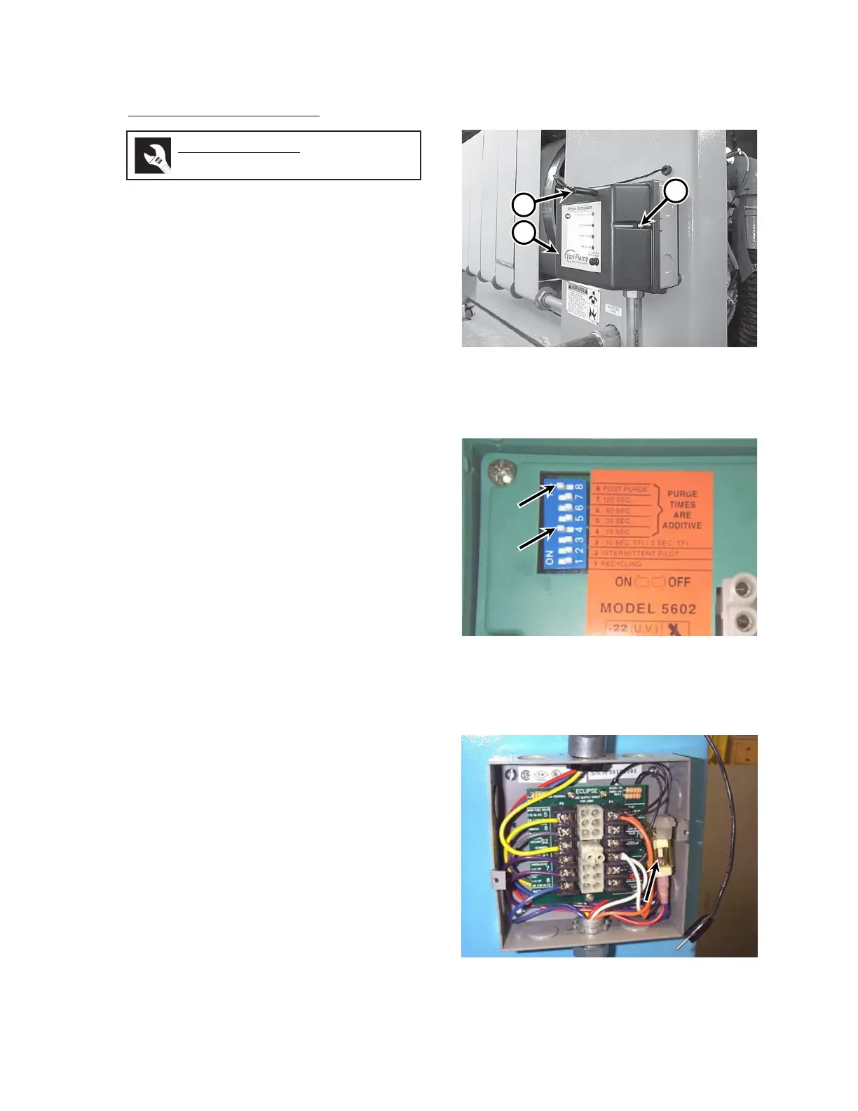
Flame Safeguard Check
The flame signal voltage probe, when plugged
into the flame safeguard, provides a 9 V to 11 V
indication on the front panel flame signal voltmeter
when a flame is sensed by the UV flame scanner.
1. Disconnect the voltage probe (Figure 2-
7, A) from the flame safeguard (B).
2. Remove the two screws that secure the
flame safeguard (Figure 2-7, C) to its base
at the rear of the unit. Carefully remove
the flame safeguard from its base.
3. Check the DIP switch settings on the
back of the flame safeguard (Figure 2-
8). Only DIP switches 4 and 8 should be
set to ON.
4. Make sure the flame signal voltmeter re-
lay is secure inside the base for the flame
safeguard (Figure 2-9).
5. Carefully plug the flame safeguard into
the connectors at the center of its base.
6. Secure the flame safeguard to its base
with the two screws that are provided.
7. Insert the voltage probe (Figure 2-7, A)
into the FLAME SIGNAL connector hole
on the top right corner of flame safeguard.
Figure 2-8: On the back of the flame safeguard,
only DIP switches 4 and 8 should be
set to ON.
Required Tools
Phillips screwdriver
Figure 2-7: The voltage probe (A) plugs into the
flame safeguard (B).
B
C
Figure 2-9: The flame signal voltmeter relay is
located on the right side of the flame
safegaurd base.
 Loading...