GL16 Repair
7-33
7.10 Burner System
Individual components of the burner system
may wear during normal use and may need
occasional repair, inspection, or adjustment. If the
burner is experiencing problems, first inspect and
clean the spark plug and pilot assembly. For more
information within this manual, go back to the
PREVENTIVE MAINTENANCE chapter,
Check/Clean Spark Plug and Pilot Assembly
procedure.
If the spark plug does not appear to be the
problem, the following procedures should be used
to maintain proper operation of the burner system:
• Pilot Air and Gas Adjustment
• Gas/Air Mixer Adjustment
• Gas/Air Mixer Cleaning
• Heat Shield Detachment From Burner
Assembly
• Replacing Heat Shield Without Removing
Burner Assembly
• Heat Shield Attachment To Burner
Assembly
• Burner Removal
• Burner Tip Maintenance
• Burner Installation
• Temperature Control Replacement
• Touchless Temperature Sensor
Replacement
• UV Flame Scanner Replacement
• UV Flame Scanner Alignment
Adjustment
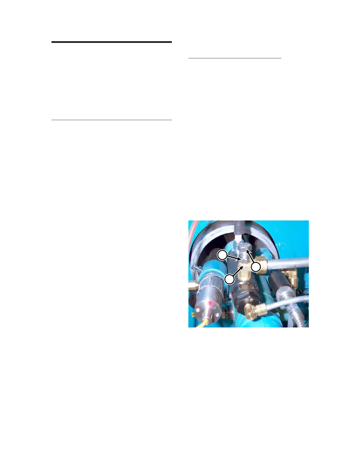
Pilot Air and Gas Adjustment
The gas pilot typically does not need adjustment.
However, with an air adjustment fitting (Figure
7-31, A) at the pilot burner combustion air
connection, the pilot flame can be adjusted for a
vigorous, reliable, and full flame.
If necessary, both the gas and combustion air
can be adjusted at the pilot. The flame length is
controlled by the manual gas valve at the pilot
valve and regulator assembly. The combustion air
can be adjusted with an adjusting screw (Figure
7-31, C) and locknut ( B) in the top of the pilot’s
brass air fitting. The flame must burn inside the
flame pipe from the spark plug to beyond the flame
pipe end. If the flame is quietly sitting on the end
of the pilot flame pipe, ignition may be unreliable.
A normal pilot flame will sound forceful.
Each gas heated unit is supplied with a manual
pilot gas valve that can be adjusted.
Figure 7-31: Adjust the pilot air and gas mixture at
fitting (A). Loosen the locknut (B)
and rotate the adjusting screw (C).
C
A
B
 Loading...