Repair GL16
7-44
UV Flame Scanner Alignment
Adjustment
For proper operation of the heating system, both
UV flame scanners must be properly aligned. The
UV flame scanner in the left end frame must
detect the pilot flame. The UV flame scanner in
the right end frame must detect the flame at the
right end of the burner.
The alignment of the UV flame scanners is set
at the factory, but it can be checked and adjusted
slightly once the unit is installed.
Checking the Alignment of a UV Flame
Scanner:
1. This procedure differs slightly, depending
on which UV flame scanner is being
tested.
• If the UV flame scanner for the pilot
flame is being tested, depress the
PILOT TEST/RESET button on the
flame safeguard (Figure 7-32) to the
IN position so that only the pilot flame
will light.
• If the UV flame scanner for the end
of burner flame is being tested, the PI-
LOT TEST/RESET button should be
in the OUT position.
2. Start the unit. Set the TEMPERATURE
CONTROL to 300ºF (150ºC), and turn the
GAS switch to ON.
3. The FLAME SIGNAL DC voltage read-
ing gives an indication of how well the
scanner sees the flame:
• FLAME SIGNAL reading of 9 V to
10 V is good
• FLAME SIGNAL reading of 6 V to
8 V is questionable
• FLAME SIGNAL reading below 6 V
is not a reliable signal.
If the FLAME SIGNAL reading is
questionable or not reliable, the align-
ment of the UV flame scanner for the
pilot flame or end of burner flame may
need to be adjusted.
Adjusting the Alignment of a UV Flame
Scanner:
1. Locate the UV flame scanner that re-
quires adjustment (Figure 7-46, A).
2. While preventing rotation of the flexible
scanner cable and the scanner, unscrew
the threaded collar from the plastic adap-
tor.
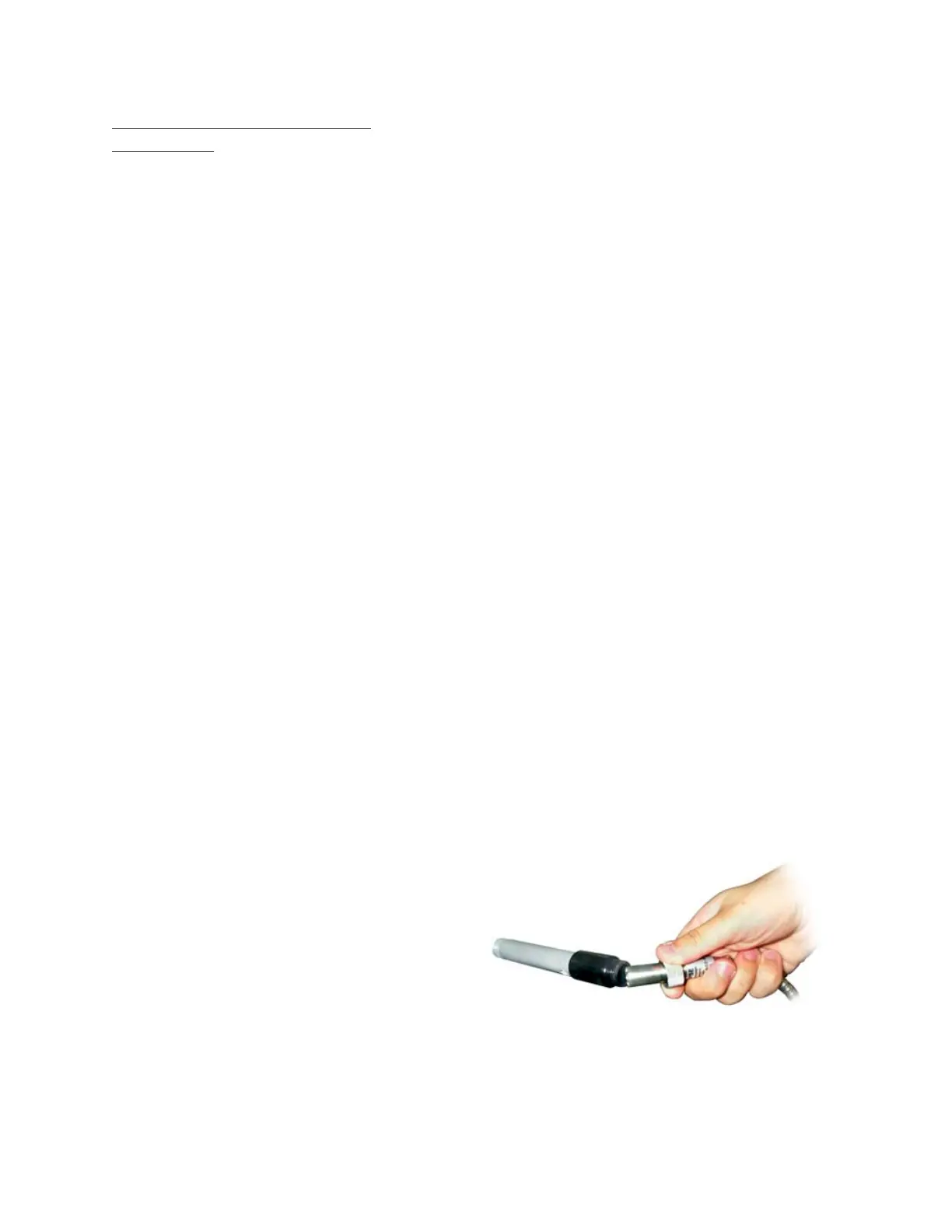
3. Hold the UV flame scanner at a slight
angle with one end touching the plastic
adaptor (Figure 7-45).
4. Look through the crescent-shaped open-
ing between the UV flame scanner and
the plastic adaptor. If the scanner is prop-
erly aligned, the flame should be visible
and centered in the tube sighting.
• If the alignment is correct, position the
UV flame scanner. While preventing
rotation of the flexible scanner cable
and the scanner, tighten the threaded
collar.
• If the alignment is incorrect, stop the
unit. Perform Steps 5 to 9 to adjust the
scanner alignment.
Figure 7-45: Hold the UV flame scanner at an angle to
view the flame through the plastic
adaptor and holding tube.
 Loading...