Repair GL16
7-20
Delivery Section Drive Belt Tension
Adjustment
The drive belt, which powers the delivery
ribbons drive roll, will stretch due to normal wear
and tear. When the belt becomes too loose to turn
the delivery drive roll, the tension must be adjusted.
1. Turn the power OFF at the main discon-
nect switch.
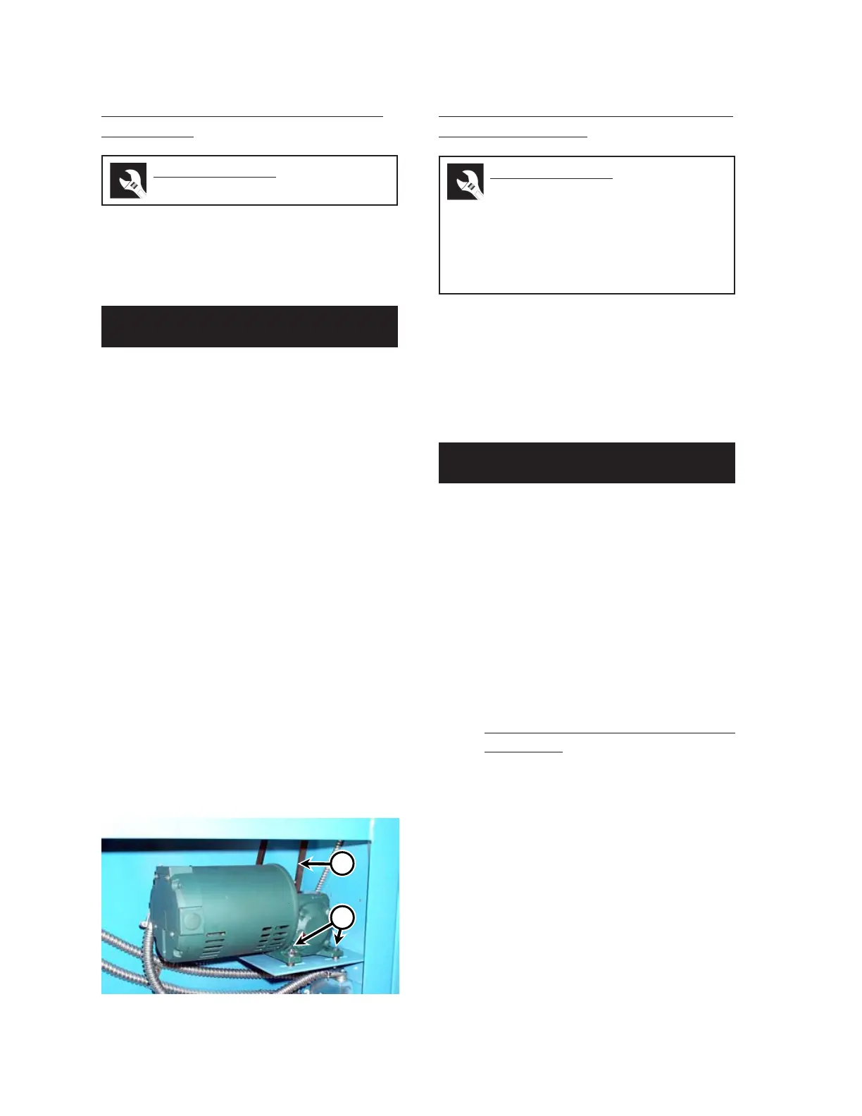
2. Open the right end frame and locate the
drive belt (Figure 7-19, A).
3. Locate the speed reducer that drives the
delivery belt. Loosen the four mounting
bolts, which connect the speed reducer to
the support bracket (Figure 7-19, B).
4. Shift the entire assembly until the belt has
proper tension. Tighten the bolts.
5. Be sure that the speed reducer pulley is
in line with the drive roll pulley so the belt
will run straight.
6. Turn the power ON at the main discon-
nect switch.
7. Press the green START button and run
the unit to verify that the belt has proper
tension and tracks straight.
Delivery Ribbons Drive Roll Tracking
Tape Replacement
Tracking tape is used to hold the canvas delivery
ribbons in proper position during operation so they
do not move laterally or start to overlap each other.
Tracking tape is positioned under the center of
each delivery ribbon and wound around the
delivery ribbon drive roll.
1. Verify there is enough 1" (25 mm) tape
available to replace the old material. One
roll of tracking tape is required for each
drive roll.
2. Turn the power OFF at the main discon-
nect switch.
3. Shift the speed reducer until the drive belt
is loose and the delivery drive roll can be
rotated by hand. For more information
within this section, go back to the
Delivery Section Drive Belt Tension
Adjustment procedure.
4. Locate the adjusting screws (Figure 7-18,
A) on the delivery idler roll. Loosen the
locknuts (B) and back off each adjusting
screw the same number of turns counter-
clockwise until the ribbons are easily
moved by hand.
5. Place a tarp, heavy paper, plastic drop
cloth or another temporary protective cov-
ering over the parts of the unit which must
be kept clean and below the work area.
Perform only when the unit is OFF
(with power disconnected) and COOL.
Perform only when the unit is OFF
(with power disconnected) and COOL.
Required Tools
wrench
Required Tools
wrench, temporary protective
covering, chain puller, drill, 3/16"
drill bit, chalk/pencil/marker,
scraper/sand paper/steel brush,
nail, pop-riveter and rivets/
screwdriver and 3/16" screws
Figure 7-19: The speed reducer assembly is shifted
to adjust delivery drive belt tension.
B
A
 Loading...