GL16 Operating Guidelines
3-5
JOG switch (F):
Moves the ironing cylinder and all ribbons in
small increments. The JOG switch turned
clockwise to the JOG FWD position will move these
elements forward a few inches. The JOG switch
turned counterclockwise to the JOG REV position
will move these elements in reverse a few inches.
When released, the JOG switch will spring back to
the center position for normal start-up and operation.
CAUTION
Set speed to slow before
using the JOG switch. Failure
to do so may result in
unsafe conditions or
damage to the unit.
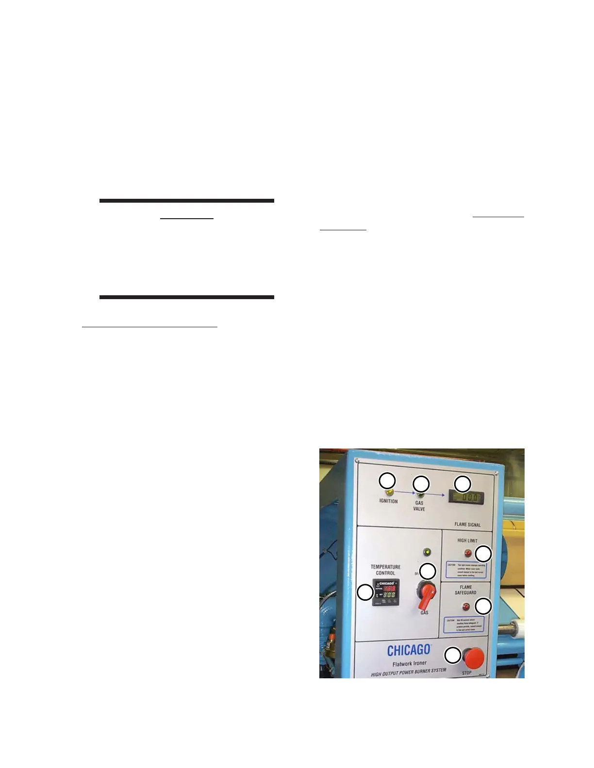
Left End Frame Controls
The following operating controls and indicator
lamps are located at the front of the left end frame
(Figure 3-7).
• TEMPERATURE CONTROL (A)
• GAS ON/OFF switch with green indicator
lamp (B)
• IGNITION yellow indicator lamp (C)
• GAS VALVE open green indicator
lamp (D)
• FLAME SIGNAL DC Voltmeter (E)
• HIGH LIMIT red indicator lamp (F)
• FLAMESAFEGUARD
red indicator lamp (G)
• STOP button (H)
TEMPERATURE CONTROL (A):
Used to set the desired operating temperature
of the ironing cylinder. When power is turned ON
at the main disconnect switch, the display will light,
and the ON indicator will be lit.
To set the desired temperature, first turn the
GAS switch ON. Then, use the increase (∧) or
decrease (∨) buttons on the TEMPERATURE
CONTROL.
The display shows the SET temperature in
green, and the ACTUAL temperature of the unit
at the sensor is shown in red. The HEAT indicator
will light when the ACTUAL temperature is lower
than the SET temperature. The
TEMPERATURE CONTROL operates from 0
to 400°F. The SEL button is not operative.
For more information within this chapter on
determining the proper operating temperatures for
different types of flatwork, proceed to the
Operating Techniques section,
Processing
Standards procedure.
GAS ON/OFF switch with green indicator
lamp (B):
Starts the ignition cycle. Turning the GAS
switch to ON enables the thermostat to control
the heating process. Turning the GAS switch to
OFF disables the heating process and closes an
open gas valve. Turning the GAS switch to OFF
is done during a faulty ignition cycle or to manually
shut off the burner flame.
Lights to indicate the GAS switch is set to the
ON position.
Figure 3-7: These operating controls are located
at the front of the left end frame.
C
D
E
F
H
B
 Loading...