Repair GL16
7-42
Temperature Control Replacement
Follow this procedure to replace the
TEMPERATURE CONTROL (Figure 7-42).
1. Turn the power OFF at the main discon-
nect switch.
2. Open the right end frame door.
3. Pull the socket from the TEMPERA-
TURE CONTROL.
NOTE: It is not necessary to
remove the wires from the
TEMPERATURE CONTROL.
4. Unscrew the two small screws on oppo-
site corners of the white/gray plastic re-
tainer around the TEMPERATURE
CONTROL.
5. Push the TEMPERATURE CONTROL
toward the front of the control panel and
pull through, while pressing the two plas-
tic retainer tabs away from the body of
the TEMPERATURE CONTROL.
6. Reverse Steps 4 and 5 to install the new
TEMPERATURE CONTROL. Make
sure the TEMPERATURE CONTROL
is upright.
7. Press the white/gray plastic retainer over
the back side of the TEMPERATURE
CONTROL.
8. Tighten the corner screws of the white/
gray plastic retainer.
9. Connect the socket to the TEMPERA-
TURE CONTROL.
10. Close and secure the right end frame door.
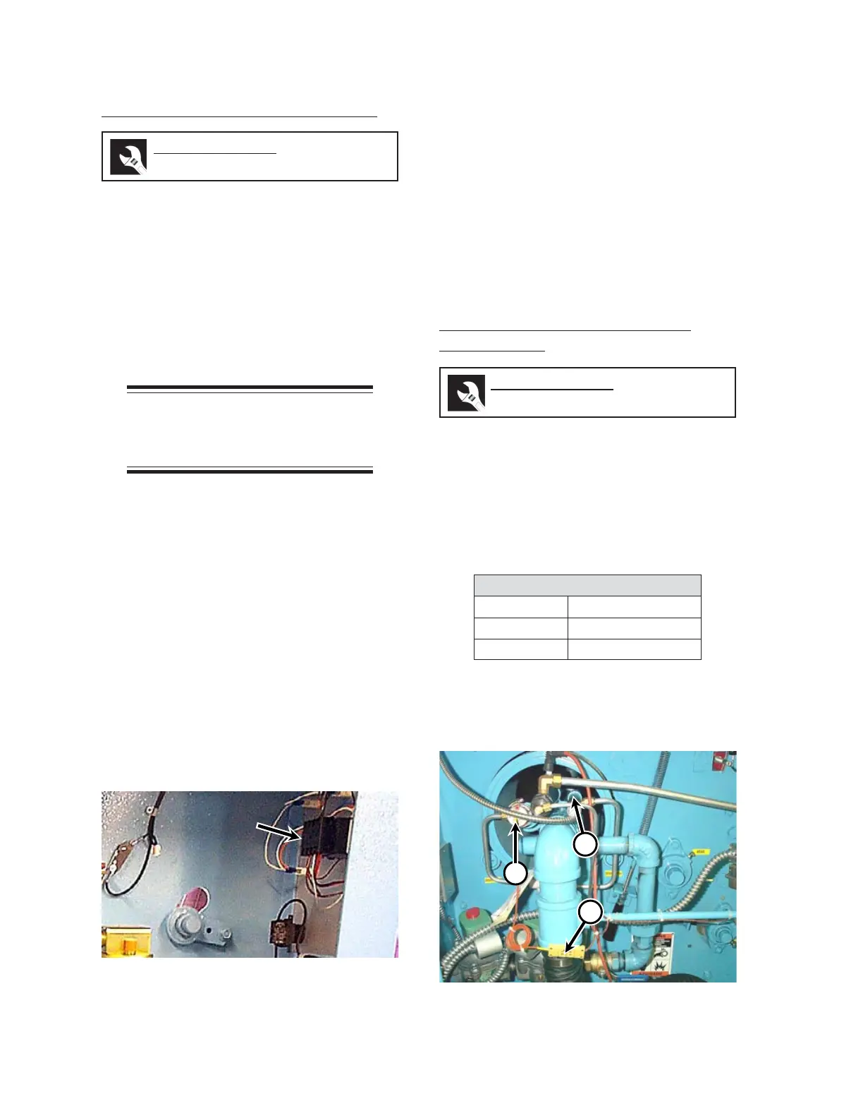
Touchless Temperature Sensor
Replacement
Each touchless temperature sensor (Figure
7-43, A) used has a 3' long thermocouple lead
wire connected to a yellow three prong male plug
connector (B) for quick connection. Each
touchless temperature sensor has the same
calibration and is interchangeable with each other.
The plug connections are as follows:
snoitcennoCgulP
wolleY)+(evitisoP
deR)-(evitageN
retneCdnuorG
1. Disconnect the yellow plug and the socket
in the touchless temperature sensor wir-
ing (Figure 7-43, B).
Figure 7-42: The TEMPERATURE CONTROL is
located inside the left end frame.
Required Tools
slotted screwdriver
Required Tools
slotted screwdriver
Figure 7-43: Touchless temperature sensors (A)
and UV flame scanners (C) are
located inside each end frame.
C
B
 Loading...