Operating Guidelines GL16
3-2
3.1 Safety Features
The unit is manufactured with several built-in
features to promote safety and proper operating
procedures.
WARNING
Never bypass any of
the safety devices.
This could result in serious
injury to operators or
maintenance personnel.
There are five general categories of safety
features:
• Main Disconnect Switch
• Safety Stop Buttons
• Safety Guards
• Safety Interlock Switches
• Safety Labels
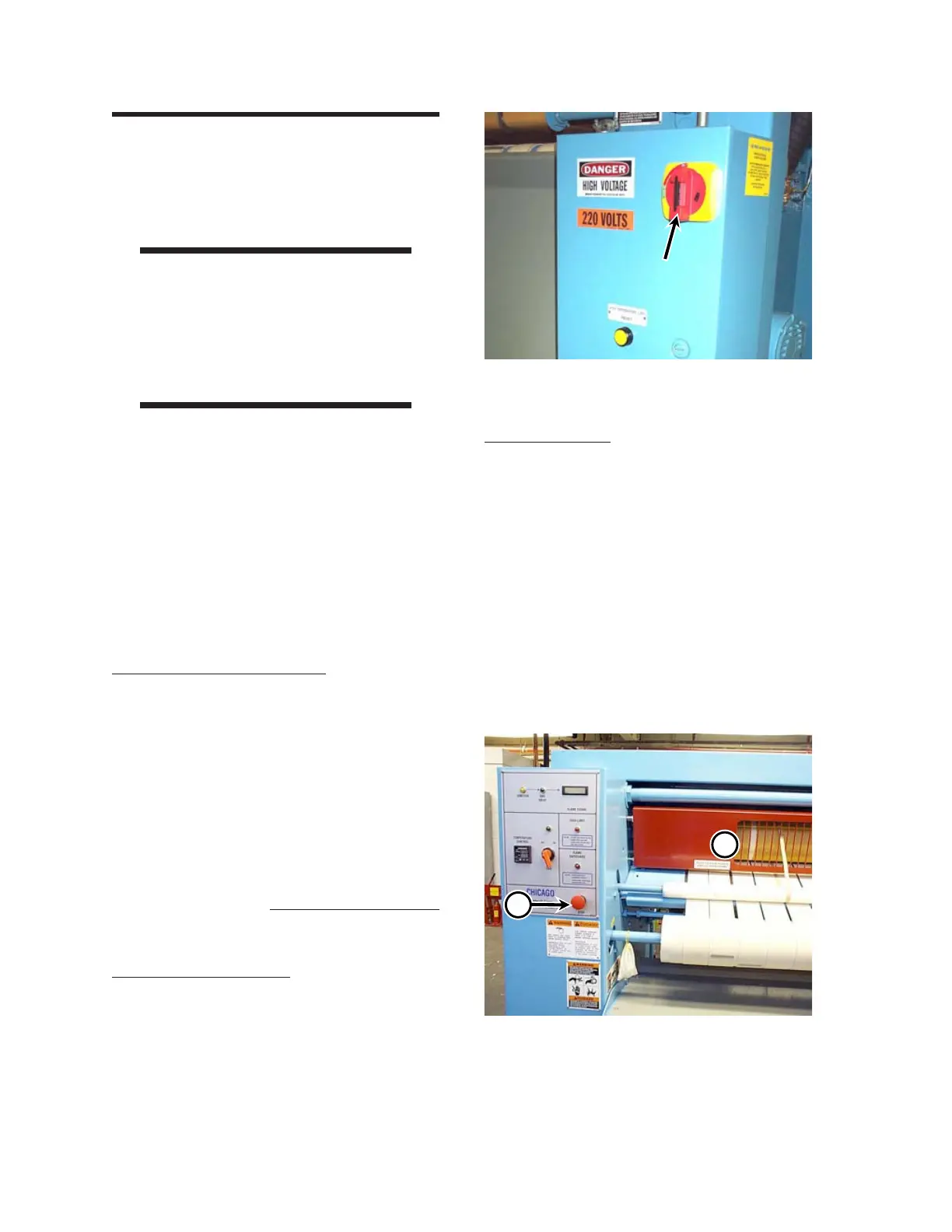
Main Disconnect Switch
The main disconnect switch (Figure 3-2) is
located on the door of the main electrical box.
When turned to OFF, the main disconnect switch
locks out the incoming electrical power to the unit.
Unless otherwise indicated, turn the main
disconnect switch to OFF before performing any
maintenance or repair work. For more information
within this manual on operating the main
disconnect switch, go back to the
INSTALLATION chapter, Installation
Procedures section, Electrical Connection
procedure.
Safety Stop Buttons
The preferred method of stopping the operation
of the unit is by pressing any of the four red STOP
buttons located at each corner of the unit (Figure
3-3, A). Pressing any of the four red STOP
buttons immediately stops all rotating parts.
Safety Guards
A red safety finger guard (Figure 3-3, B) covers
the moving parts at the front of the unit. It runs
the entire length of the working area and
physically restricts hands from coming into contact
with moving and heated parts. Pushing the safety
finger guard immediately stops all rotating parts.
Both end frames and the rear of the unit are
covered with protective panels to prevent fingers
or hands from coming into contact with moving
and heated parts. When a panel is removed, all
rotating parts stop moving.
Figure 3-3: The red STOP buttons (A) and red
safety finger guard (B) provide
immediate shut-down capability
B
A
Figure 3-2: The main disconnect switch is
located on the main electrical box.
 Loading...