Installation GL16
2-16
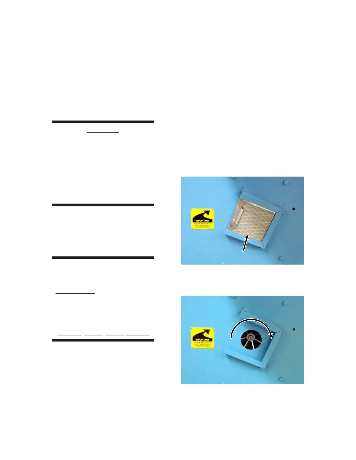
Figure 2-24: The combustion blower motor should
be turning in the direction of the
arrow on the blower housing.
Figure 2-23: The air filter for the combustion
blower motor is located on the left
end frame.
Electrical Connection Checkout
After all utility connections are completed, the
unit can be energized and checked for proper
electrical operation. All maintenance procedures
should be handled by at least two qualified persons.
Using the “buddy system” decreases the risk of
an accident.
Combustion Blower Rotation
CAUTION
Do not use the feed ribbon
direction of travel to indicate
correctness of the electrical
connection. The AC
frequency inverter controls
direction. Use the
combustion blower motor
rotation as the indicator.
Follow these steps to check for proper rotation
of the combustion blower motor.
1. Turn the power OFF at the main discon-
nect switch.
WARNING
The safety interlock switch
is only to be defeated
temporarily while performing
this procedure. Never
operate the unit unless
all safety systems are
working correctly.
Serious Injury Could Result.
2. Open the left end frame door. This opens
a safety interlock switch. Normally, the
unit will not operate when a safety inter-
lock switch is open. As a temporary mea-
sure during this checkout, defeat the safety
interlock switch.
3. Remove the combustion blower air filter
(Figure 2-23).
4. Make sure the gas supply to the unit is
turned off.
5. Turn power ON at the main disconnect
switch. Start the unit by pressing the green
START button.
6. Look at the rotation direction of the com-
bustion blower motor (Figure 2-24). Turn
the GAS switch to ON. Increase the
temperature on the TEMPERATURE
CONTROL until the combustion blower
motor cycles on and then immediately
press a STOP button.
 Loading...