Repair GL16
7-12
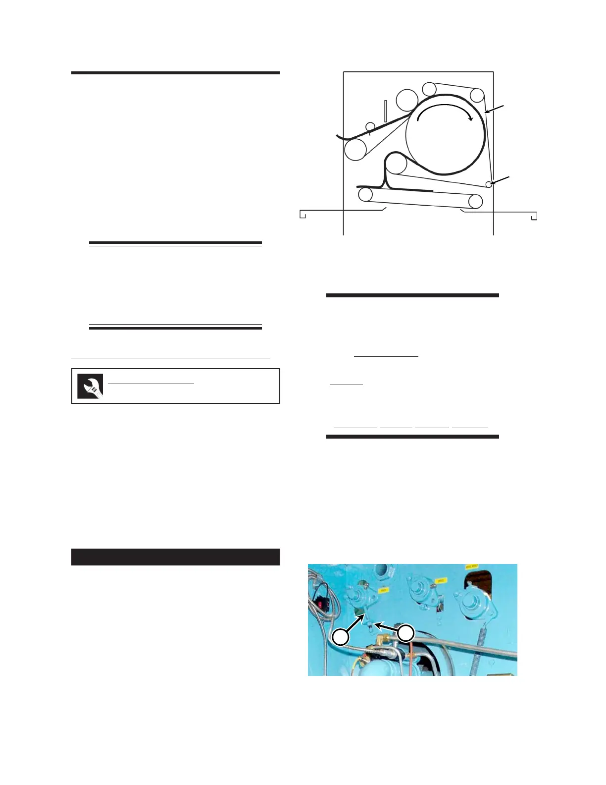
7.4 Return Section
Flatwork is directed through the ironing section
by the return section (Figure 7-12). The return
section consists of the following components:
• Return ribbons (A)
• Idler rolls (B)
• Return ribbon guide assembly (C)
• Return ribbon drive roll (D)
NOTE: Read the Pink
Operator Safety sheet,
RETURN RIBBON REPLACE-
MENT REMINDER located in the
front of this manual.
Return Ribbon Tension Adjustment
The tension of the return ribbons on the return
ribbon guide assembly needs to be adjusted when
the ribbons begin to sag. Chains and springs are
attached to each guide assembly bearing and are
anchored by adjustment screws.
When the return ribbons begin to sag, first make
sure the guide assembly is free to move. If that is
not the problem, the tension on the return ribbon
guide assembly must be adjusted.
1. Turn the power OFF at the main discon-
nect switch.
2. Open both end frame doors. The unit will
not operate while the safety interlock
switches are open. As a temporary mea-
sure during this procedure, defeat the
safety interlock switch in each end frame.
WARNING
The safety interlock switches
are only to be defeated
temporarily while the
procedure is being done.
Never operate the unit unless
all safety systems are
working correctly.
Serious Injury Could Result.
3. Locate the adjusting screws (Figure 7-13,
A) inside both end frames which secure
each return ribbon drive roll bearing in po-
sition. Loosen the locknuts (B), while
holding the screws in place, and adjust
each screw the same number of turns
clockwise until the ribbons are snug
against the drive roll.
Perform only when the unit is COOL.
Required Tools
wrench
Figure 7-12: The return ribbons and their drive
roll move the flatwork against the
ironing cylinder.
B
B
A
C
D
Ironing
Cylinder
Figure 7-13: The return ribbon guide assembly
adjustment screws (A) and locknuts
(B) are located inside each end frame.
B
 Loading...