GL16 Repair
7-41
Burner Tip Maintenance
1. Remove the burner. For more informa-
tion within this section, go back to the
Burner Removal procedure.
2. Place the burner assembly on a sturdy
worktable.
NOTE: To prevent distortion of
the burner tips, it is necessary to
insert a short, round steel shaft or
bar into the top of the burner tip
that just fits and can be easily
removed.
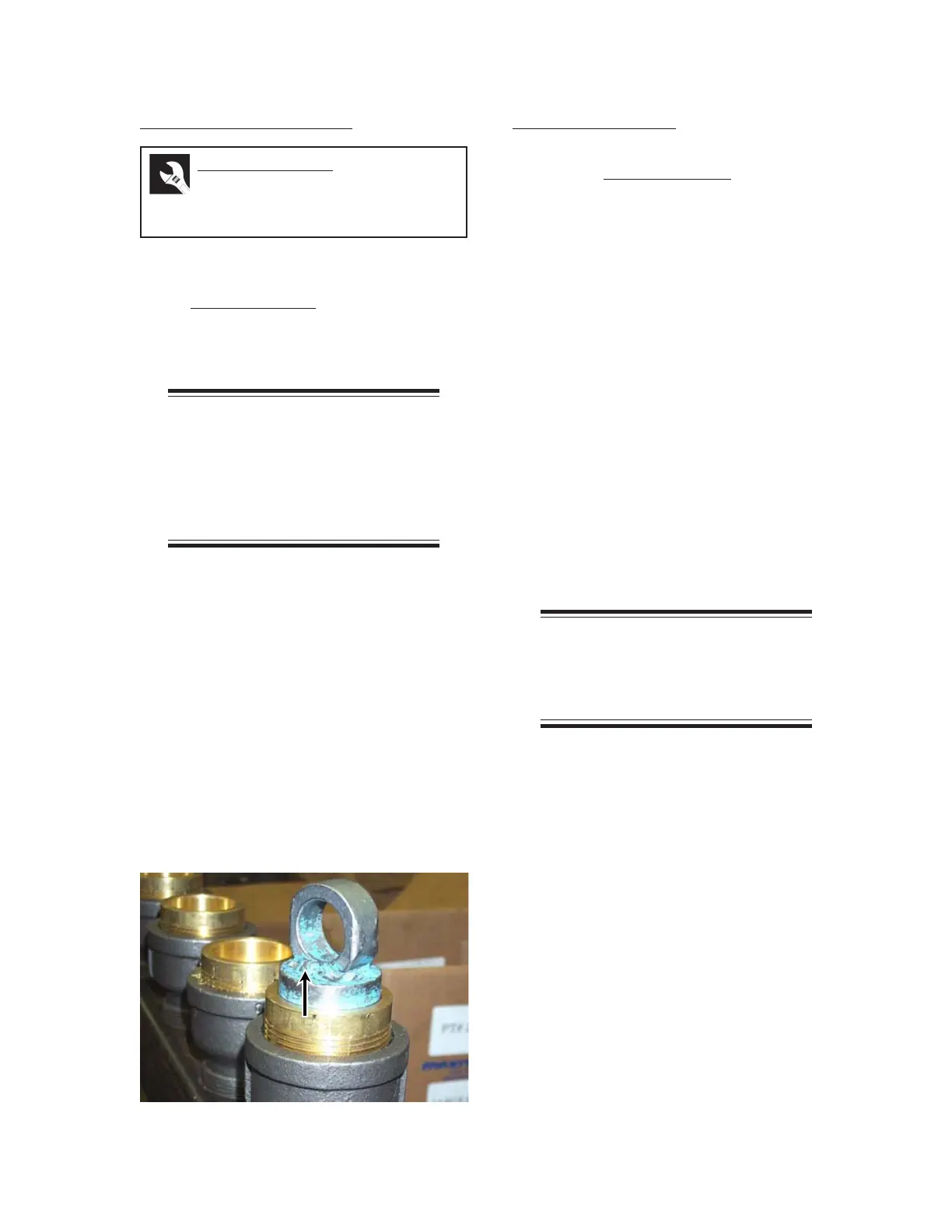
3. Place a steel insert with a diameter of
1.490" ± 0.005" (37.85 mm ± 0.13 mm)
into the first burner tip (Figure 7-40) so
the tip does not bend or get stripped. Use
a chain wrench to remove the burner tip.
Repeat this process for the remaining
burner tips.
4. Blow out each tip with compressed air
from the top and bottom.
5. Use compressed air to blow out the burner.
6. Install each burner tip using the steel in-
sert and chain wrench.
Burner Installation
To reinstall the burner assembly, reverse the
steps in the Burner Removal procedure and
refer to the following additional guidelines:
• When the assembly has been pushed
back into the ironing cylinder, use the 1" x
4' (25 mm x 1220 mm) pipe to help guide
the tail pipe into place. With two people
at the left end frame pushing down
slightly on the burner assembly, a third
person needs to reach into the ironing
cylinder from the right end frame to pull
the end of the pipe over the tail pipe.
• Once the tail pipe is seated in the
1" x 4' (25 mm x 1220 mm) pipe, lift up
the burner assembly at the left end frame
and slide it the rest of the way into
position. Remove the pipe and finish
installing the burner assembly.
• After the burner is installed, start the unit
to verify proper operation.
NOTE: If the gas pressure
needs to be adjusted, go back to
the INSTALLATION chapter, Gas
Connection Checkout section.
Required Tools
chain wrench, steel insert with
a diameter of 1.490" ± 0.005"
(37.85 mm ± 0.13 mm)
Figure 7-41: Prevent burner tip distortion with a
steel insert.
 Loading...