GL16 Installation
2-15
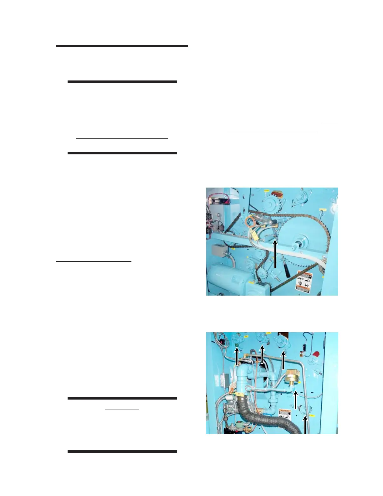
Figure 2-21: The machine speed sensor must be
correctly positioned near the teeth of
the ironing cylinder sprocket.
2.3 Pre-Operational
Checkout
WARNING
Understand the OPERATING
GUIDELINES chapter,
Operating Controls section
before starting any of the
Pre-Operational Checkout
procedures.
Before the unit can be placed into full operation,
perform the following procedures:
• Security of Hardware
• Electrical Connection Checkout
• Control Function Checkout
• Gas Connection Checkout
• Checkout Completion
Security of Hardware
1. Open the doors on both end frames.
2. The machine speed sensor is located in
the right end frame (Figure 2-21). It is
mounted on a bracket very close to the
teeth of the ironing cylinder sprocket. The
unit starts but will shut down after 5 sec-
onds if this sensor has moved from the
correct position. Check that the sensor is
0.06" (1.5 mm) from the teeth of the
sprocket. For information within this
manual on adjusting the position of the
sensor, proceed to the REPAIR chapter,
Machine Speed Sensor Adjustment
section.
CAUTION
Do NOT put setscrews into
the left end frame bearings—
this allows for heat
expansion (Figure 2-22).
3. Check all hardware connections and
tighten as necessary. Check that all set-
screws are sufficiently tightened to hold
their respective components in position.
4. Make sure all protective wrappers and
wooden wedges holding the ironing cylin-
der are removed. For more information
within this chapter, go back to the
Installation Procedures section,
Final
Protective Wrapper Removal proce-
dure.
5. Close and secure both end frames.
Figure 2-22: Do NOT put setscrews into left end
frame bearings.
 Loading...