Repair GL16
7-36
Heat Shield Detachment From
Burner Assembly
1. Turn power OFF at the main disconnect
switch.
2. Remove rear panel of the unit.
NOTE: Wear gloves to protect
hands from sharp edges.
3. Reach into one end of the ironing cylin-
der. Flip the pin ring and slowly pull out
the pin. (Figure 7-36).
4. Slide the heat shield from the eye hook
and let the end of the heat shield rest on
the bottom of the ironing cylinder.
5. Repeat Steps 3 and 4 for the other end of
the heat shield.
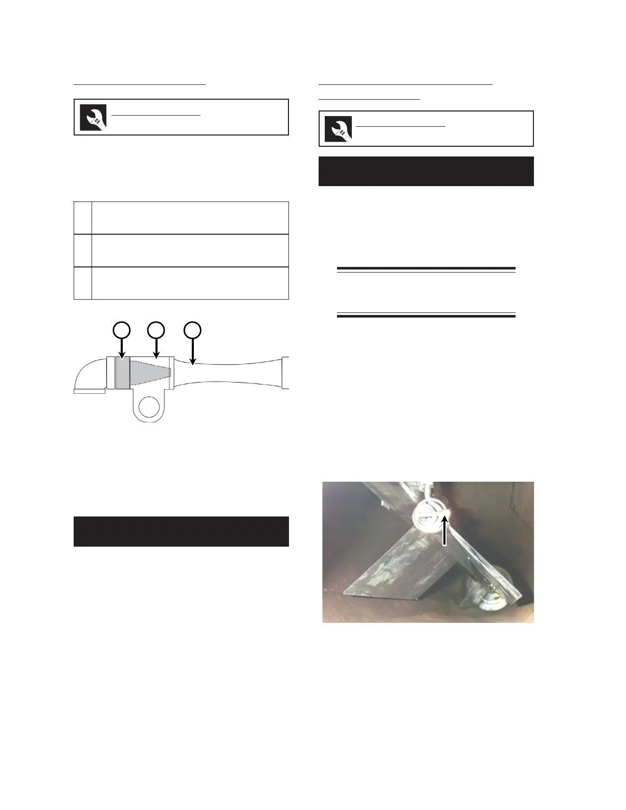
Gas/Air Mixer Cleaning
The inside of the gas/air mixer should be cleaned
when the burner is cleaned. The mixer consists
of three parts that are screwed together to form
a complete unit (Figure 7-35):
To clean the mixer, it should only be necessary
to clean the inside and outside surfaces of the air
injector ( Figure 7-35, A).
1. Turn power OFF at the main disconnect
switch.
2. Unscrew the air injector, with the air el-
bow and piping still connected.
3. Clean the inside and outside surfaces of
the air injector.
4. If necessary, remove and clean the re-
maining two sections of the mixer.
5. Assemble the gas/air mixer. Thread com-
pound is not required on the threads.
Perform only when the unit is OFF
(with power disconnected) and COOL.
Required Tools
wrench
Required Tools
gloves, wrench, slotted screwdriver
Perform only when the unit is OFF
(with power disconnected) and COOL.
A
-rotcejnIriA tnenopmocdepahsenoC
.reximehtotniriaswollataht
B
-ydoB/telnIsaG ehtmorfsretnesaG
.rotcejniriaehtsdnuorrusdnaedis
C
-irutneV si)A(rotcejniriamorfriA
.)B(ydobehtsagehthtiwdexim
Figure 7-35: The Gas/Air Mixer is composed of
three sections.
AB C
Figure 7-36: Disconnect the heat shield by
removing retaining pin at each end.
 Loading...