GL16 Repair
7-29
7.8 Machine Speed Sensor
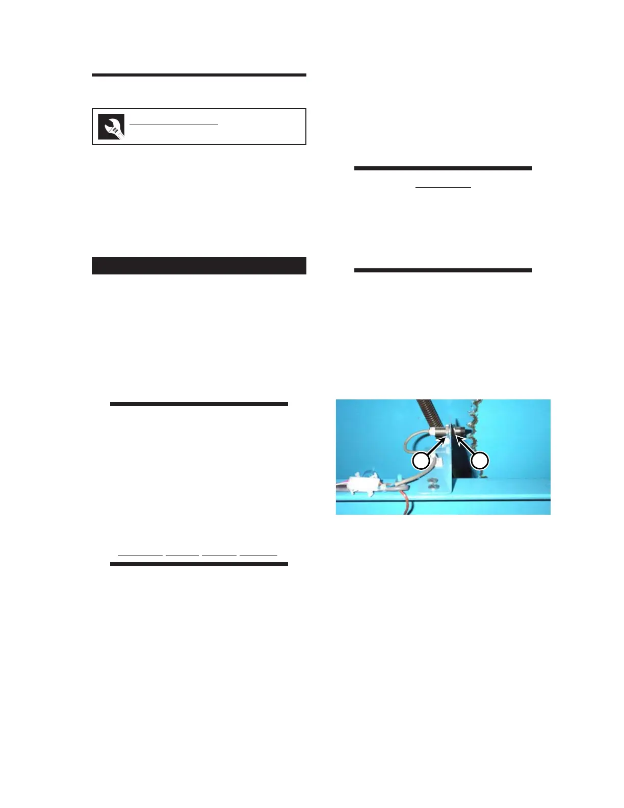
The machine speed sensor (Figure 7-29) is
located inside the right end frame. It is mounted
on a bracket very close to the teeth of the ironing
cylinder sprocket. This sensor generates a
magnetic field, which is disturbed by each passing
tooth of the sprocket. This signal is interpreted as
the speed of the flatwork.
1. Turn the power OFF at the main discon-
nect switch. Open the right end frame
door.
2. The unit will not operate while a safety
interlock switch is open. As a temporary
measure during this procedure, defeat the
door switch in the end frame.
WARNING
The safety interlock switches
are only to be defeated
TEMPORARILY while the
procedure is being done.
NEVER operate the unit
unless all safety systems are
properly installed and
working correctly.
Serious Injury Could Result.
3. Turn the power ON at the main discon-
nect switch. Press the green START but-
ton. Turn the SPEED knob to the slowest
speed.
4. Look at the machine speed sensor (Fig-
ure 7-29). The LED on the back of the
sensor should blink each time a tooth of
the ironing cylinder sprocket passes.
5. Press a red STOP button. Turn the power
OFF at the main disconnect switch. If the
LED is not blinking, the sensor may be
located too far from the teeth of the
sprocket. The gap between the sensor and
the teeth should be 0.06" (1.5 mm).
CAUTION
Adjust the position of the
machine speed sensor very
carefully. If it is hit by the
sprocket, the sensor
must be replaced.
6. Loosen outer nut (Figure 7-29, A) and
move the sensor closer to the teeth.
Tighten inner nut (B) to hold the sensor in
the new position. Do not position the sen-
sor closer than 0.04" (1.0 mm) to the
sprocket. The sensor must be replaced if
it is hit by the teeth of the sprocket.
7. Repeat Steps 3 to 6 until the machine
speed sensor is operating correctly.
8. Press a red STOP button. Turn the power
OFF at the main disconnect switch. Close
the end frame door.
Perform only when the unit is COOL.
Figure 7-29: Adjust the position of the machine
speed sensor with outer nut (A) and
inner nut (B).
A
B
Required Tools
wrench, ruler/tape measure
 Loading...