Operating Principles GL16
5-6
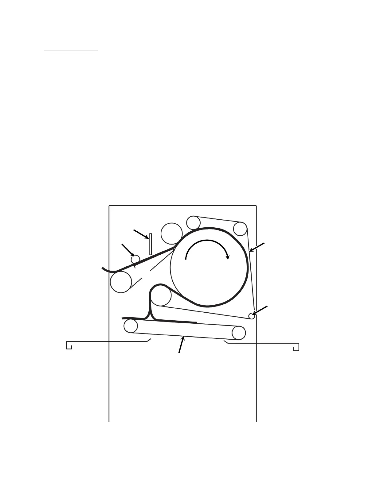
Ironing Section
The other components of the mechanical
system are the rolls and ribbons which move the
flatwork through the unit. Use the cross-section
below (Figure 5-4) to follow the path of the
flatwork. Note the function of each roll and set
of ribbons as the flatwork moves through the unit.
Flatwork Path—Type F and R Units
1. Feed ribbon drive roll (A) rotates the set
of feed ribbons (B).
2. Feed ribbons (B) move the flatwork under
the doffer roll (C) and the safety finger
guard (D) toward the ironing cylinder (F).
3. Flatwork is then carried under the spring-
tensioned compression roll (E), which
smooths and flattens the flatwork.
4. To keep the flatwork tight against the iron-
ing cylinder (F), a set of return ribbons
(G) is rotated by the return ribbon drive
roll (H) and guided by the return ribbon
guide assembly (K) and the idler rolls (J).
Flatwork Delivery Path—Type R Unit
Delivery ribbons (L) are rotated by the delivery
drive roll (M) and idler roll (N).
The delivery drive motor is reversible, and the
delivery ribbons can discharge the flatwork to the
front or rear of the unit.
Figure 5-4: Cross-section of mechanical components. The flatwork path
through the ironing section is indicated by the bold line.
A
L
H
N
M
K
C
D
E
F
Ironing
Cylinder
J
J
G
B
 Loading...