Installation GL16
2-4
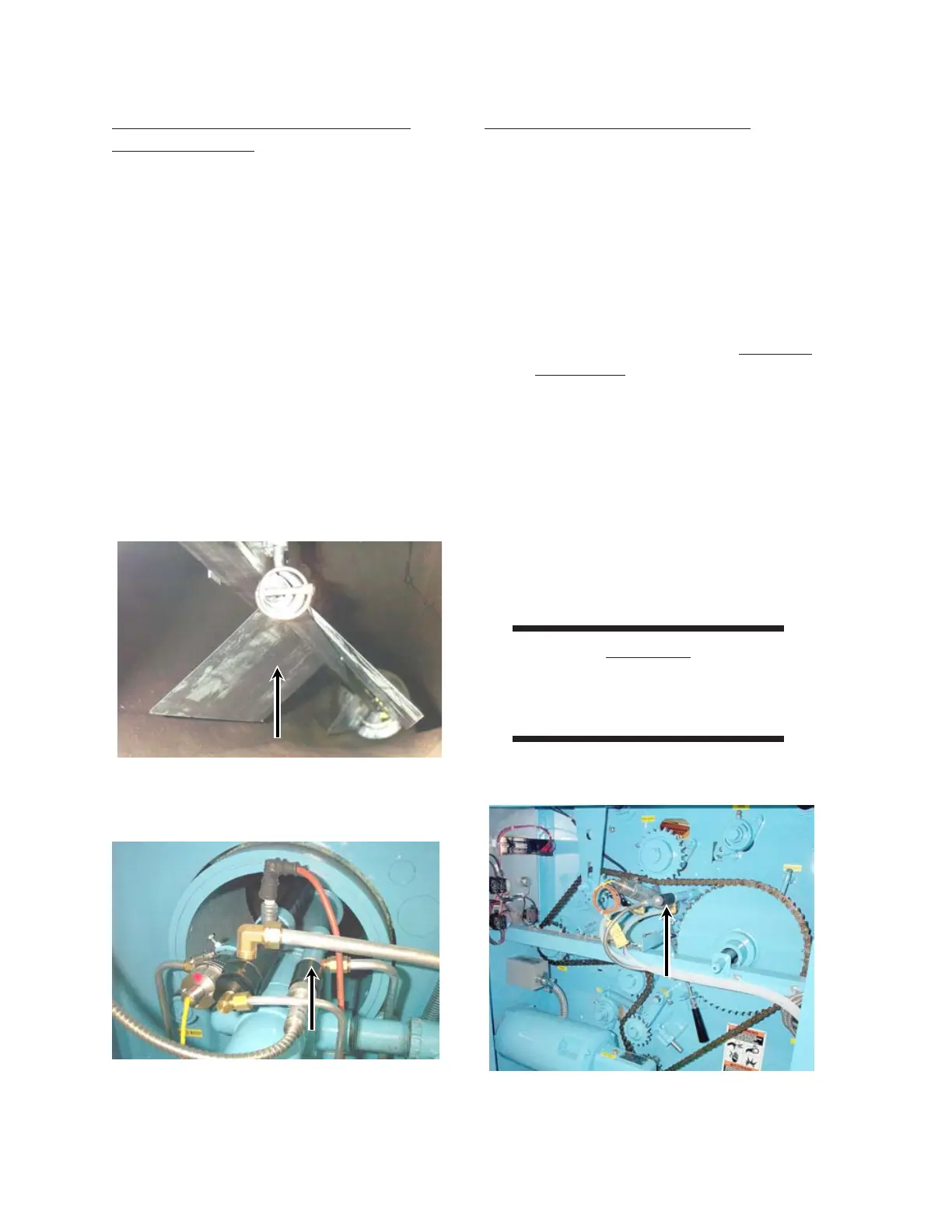
Check The Heat Shield Inside The
Ironing Cylinder
The heat shield must be placed properly to allow
the touchless temperature sensors to measure the
heated cylinder temperature without being
affected by the high heat energy radiating from
the burner flame.
Open both end frame doors and make sure that:
1. The shield hangs freely and does not rub
or touch the inside of the ironing cylinder
(Figure 2-4).
2. The clearance between shield and cylin-
der wall measures approximately 3/8" to
1/2" (10 to 13 mm).
3. The shield is suspended securely, and the
retainers are in place.
UV Flame Scanner Installation
The UV flame scanners are used to monitor
the presence of a pilot flame at the left end of the
burner and the burner flame at the right end of
the burner. The UV flame scanners send signals
to the flame safeguard.
To install the UV flame scanners:
1. Turn the power OFF at the main discon-
nect switch. For more information within
this chapter proceed to the
Electrical
Connection procedure, Main Power
Connection.
2. Locate the bubble-wrapped UV flame
scanner inside each end frame.
3. Carefully remove the bubble wrap from
the UV flame scanners.
4. Be careful not to touch the scanner’s lens.
5. Carefully screw each UV flame scanner
into its socket (Figures 2-5 and 2-6).
CAUTION
Do not allow the UV flame
scanner to strike any object.
Damage may occur.
Figure 2-6: The UV flame scanner for the flame
at the end of the burner is located
inside the right end frame.
Figure 2-5: The UV flame scanner for the pilot
flame is located inside the left end
frame.
Figure 2-4: The heat shield is located inside the
ironing cylinder.
 Loading...