GL16 Repair
7-43
UV Flame Scanner Replacement
NOTE: Never twist the cable
attached to the UV flame
scanners.
1. Open the junction box attached to the UV
flame scanner wires. Observe which wires
are connected to the scanner, and then
remove the wire nuts attaching the wires.
2. To remove the UV flame scanner, pre-
vent rotation of flexible scanner cable and
unscrew the UV flame scanner from the
holding tube.
3. Carefully screw the new UV flame scan-
ner into the holding tube.
CAUTION
Do not let the scanner
strike anything or be struck
by anything. Striking the
scanner on a hard
surface can cause
permanent damage.
4. Connect the wires for the new UV flame
scanner in the junction box and tighten the
wire nuts.
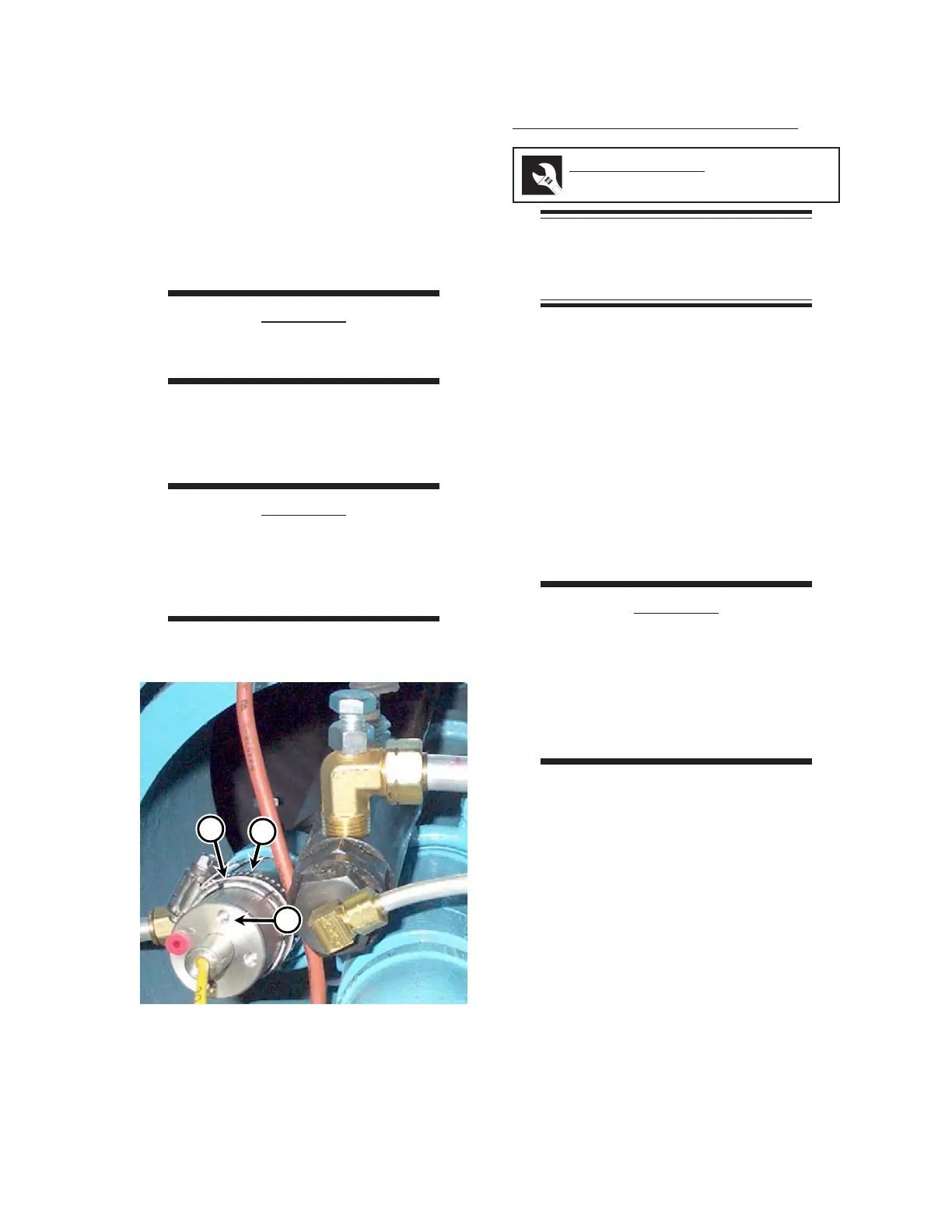
2. Loosen the clamp (Figure 7-44, A) and
carefully remove the touchless tempera-
ture sensor (C) from the holding tube (B).
Place the sensor in a safe location.
3. Carefully position the new touchless tem-
perature sensor in the holding tube (Fig-
ure 7-44, B), and tighten the clamp (C).
CAUTION
The touchless temperature
sensor is extremely fragile.
4. Connect the yellow plug and the socket in
the touchless temperature sensor wiring
(Figure 7-43, B).
CAUTION
Do not apply electrical power
to the sensor connections.
This will harm the unit and
will void the part warranty
Required Tools
wrench
Figure 7-44: The clamp (A) and holding tube (B)
hold the touchless temperature
sensor (C) in place.
A
B
C
 Loading...