EasyManuals Logo

LaserLine Flatwork Ironer Series User Manual

Default Icon
238 pages
To Next Page IconTo Next Page
To Previous Page IconTo Previous Page
Page #165 background imageLoading...
Page #165 background image
GL16 Repair
7-45
5. Remove the plastic adaptor from the scan-
ner holding tube.
6. Attach a 1/2" pipe coupling and pipe nipple
to the end of the scanners holding tube.
7. Apply pressure slightly to realign the hold-
ing tube.
8. Remove the 1/2" pipe from the holding
tube.
9. Install the plastic adaptor on the holding
tube.
10. Repeat Steps 3 and 4 to check the new
alignment of the UV flame scanner.
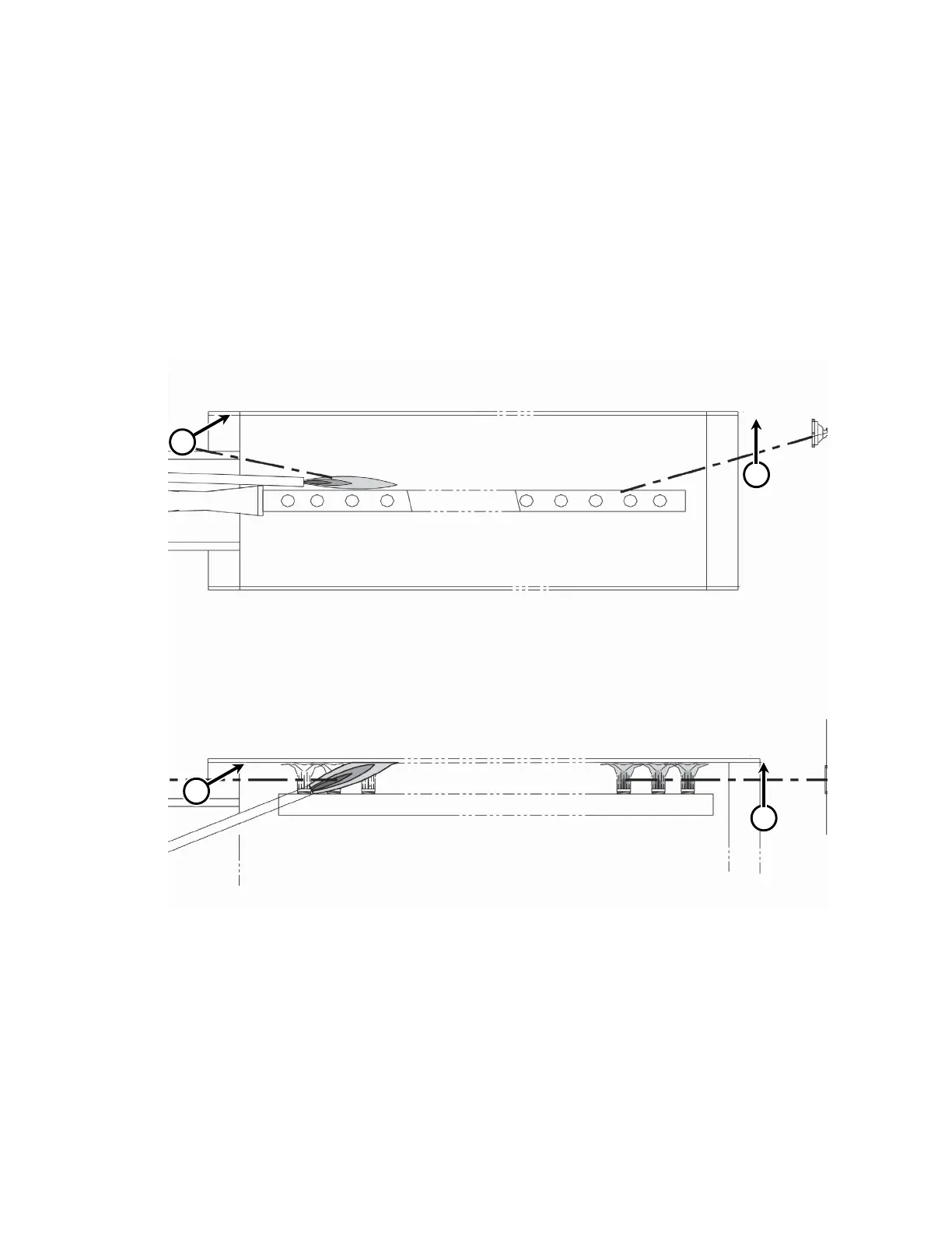
Figure 7-46: The UV flame scanners (A) must be adjusted to detect the pilot flame and the flame
at the end of the burner.
TOP VIEW
FRONT VIEW
A
A
A
A

Table of Contents

Questions and Answers:

Question and Answer IconNeed help?

Do you have a question about the LaserLine Flatwork Ironer Series and is the answer not in the manual?

LaserLine Flatwork Ironer Series Specifications

General IconGeneral
BrandLaserLine
ModelFlatwork Ironer Series
CategoryIron
LanguageEnglish