Installation GL16
2-12
Required Tools
wrench, pipe joint compound
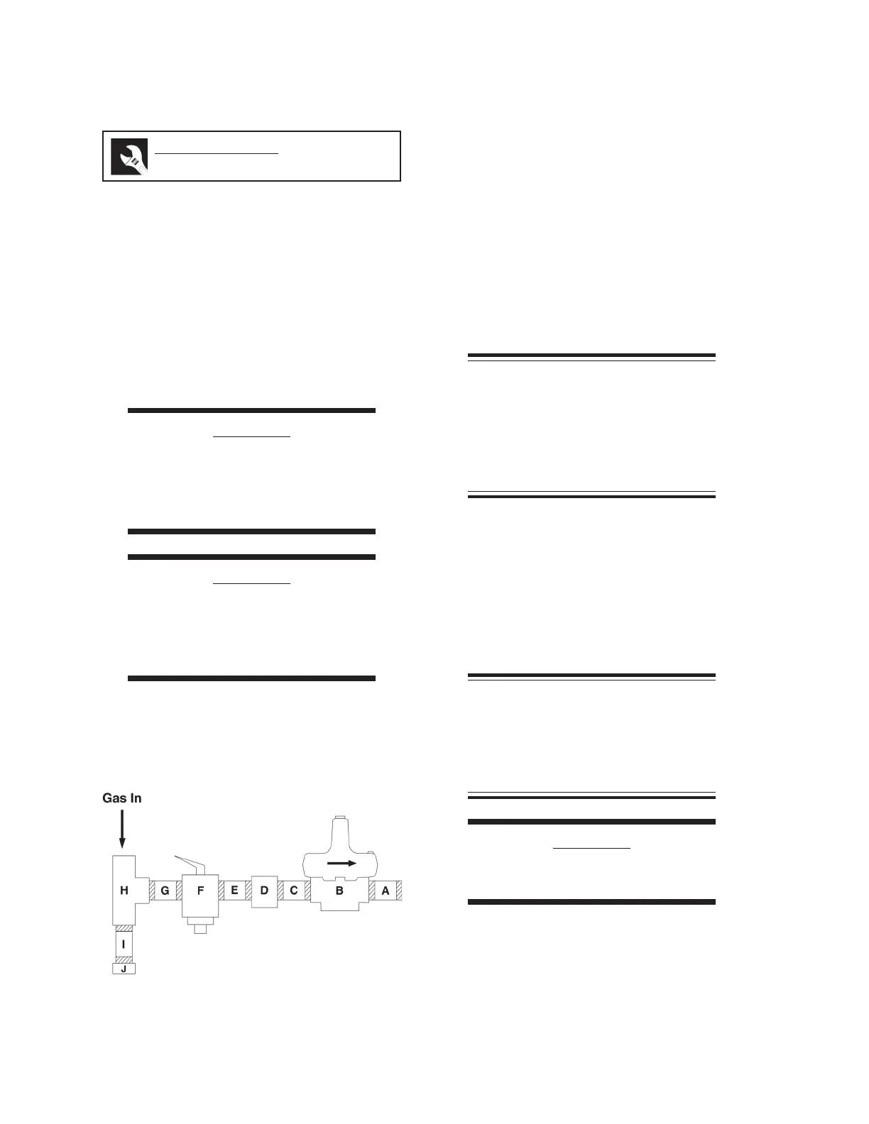
Figure 2-18: Install the hardware for the gas
connection as shown.
Regulator and Valve Installation
The gas line to the unit should be routed so it
does not interfere with any service panel or block
access to the back of the unit.
1. Check all internal gas connections in the
unit. Tighten any unions that became loose
during shipment.
2. Connect the short nipple (Figure 2-18, A)
to the coupling at the back of the left end
frame.
CAUTION
The regulator must be
installed so the gas flow is in
the direction of the arrow on
the regulator.
CAUTION
The regulator must not be
installed upside down.
The regulator must be
installed horizontally.
3. Carefully note the direction of the arrow
on the regulator (B). At the point of the
arrow, connect the discharge side of the
regulator to the short nipple (A).
4. Connect a short nipple (C) to the inlet of
the regulator (B). Connect the female half
of union (D) to the short nipple (C).
5. Connect short nipples (E and G) on either
side of gas valve (F). Connect the male
half of union (D) to one of the nipples
(E or G), and connect the branch of tee
(H) to the other nipple. Install the tee ver-
tically.
6. Attach a dirt leg nipple (I) with a cap (J)
to the lower run of the tee (H).
NOTE: A dirt leg in the gas line
upstream of the gas pressure
regulator helps prevent
malfunctions resulting from rust,
grit, dirt, and other solid particles
in the gas supply.
7. Connect the two halves of union (D).
8. Make sure the manual gas valve (F) is
closed, by rotating the handle to a 90° angle
from the length of the gas pipe.
9. Extend the gas supply line to the top of
the tee (H).
NOTE: If possible, extend the
gas supply line directly from the
gas meter to the unit without any
other equipment connected to this
line.
CAUTION
Do not open any gas valves
at this time.
 Loading...