• “Install a rearwall bracket” on page 122
Rearwall bracket matrix
Server rear
config.
Required rearwall brackets
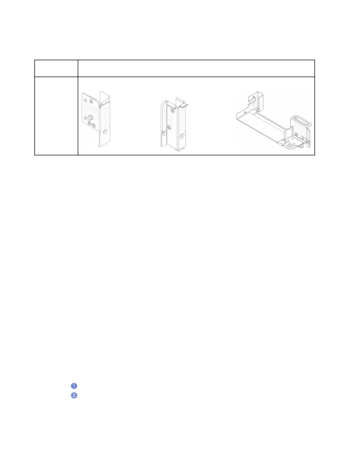
Configuration
with 6 PCIe
slots
A1 rearwall bracket on the left
B1 rearwall bracket on the
middle
C1 rearwall bracket on the right
Remove a rearwall bracket
Follow instructions in this section to remove a rearwall bracket.
About this task
Attention:
• Read
“Installation Guidelines” on page 35 and “Safety inspection checklist” on page 36 to ensure that you
work safely.
• Power off the server and peripheral devices and disconnect the power cords and all external cables. See
“Power off the server” on page 42.
• Prevent exposure to static electricity, which might lead to system halt and loss of data, by keeping static-
sensitive components in their static-protective packages until installation, and handling these devices with
an electrostatic-discharge wrist strap or other grounding system.
Watch the procedure
A video of this procedure is available at YouTube:
https://www.youtube.com/playlist?list=PLYV5R7hVcs-
BashWCNZQEDP7o3EohXPEV
.
Procedure
Step 1. Make preparation for the task.
a. If the server is installed in a rack, slide the server out on its rack slide rails to gain access to the
top cover, or remove the server from the rack. See
“Remove the server from rack” on page 43.
b. Remove the top cover. See
“Remove the top cover” on page 148.
c. Remove the riser assembly or rear drive cage.
•
“PCIe adapter and riser assembly replacement” on page 88
Step 2. Remove the rearwall bracket.
a.
Remove the screws.
b.
Remove the bracket from the chassis as shown.
Note: The illustrations show removing the A1, B1, and C1 rearwall brackets. The procedure is the
same for removing other rearwall brackets.
120
ThinkSystem SR655 V3 User Guide