EasyManuals Logo

Lenovo ThinkSystem SR655 V3 User Manual

Lenovo ThinkSystem SR655 V3
256 pages
To Next Page IconTo Next Page
To Previous Page IconTo Previous Page
Page #30 background imageLoading...
Page #30 background image
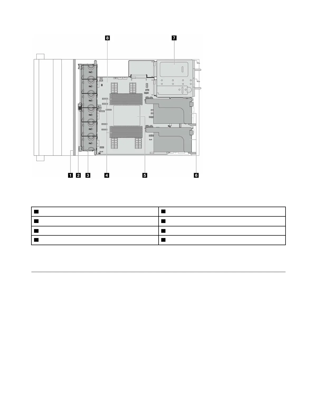
Figure 5. Server top view
Table 7. Component identification (top view)
1 Front backplane(s)
2 Intrusion switch
3 System fans
4 Memory modules
5 Processor and heat sink 6 Riser assemblies
7 Power supply unit 8 system board assembly
Note: The illustration shows the server rear configuration with two riser assemblies. The server rear
configurations vary by server model. For details, see
“Rear view” on page 18.
System-board-assembly layout
This section provides information about the connectors, switches, and jumpers that are available on the
system board assembly.
The following illustration shows the layout of the system board assembly that contains the system I/O board,
firmware and RoT security module, fan board, power inverter board (PIB) and processor board.
20
ThinkSystem SR655 V3 User Guide

Table of Contents

Questions and Answers:

Question and Answer IconNeed help?

Do you have a question about the Lenovo ThinkSystem SR655 V3 and is the answer not in the manual?

Lenovo ThinkSystem SR655 V3 Specifications

General IconGeneral
ProcessorAMD EPYC 9004 Series
Form Factor2U rack server
MemoryUp to 6TB
Memory Slots24 DIMM slots
StorageUp to 24 x 2.5" or 12 x 3.5" drives
NVMe SupportYes
NetworkingMultiple 1Gb/10Gb/25Gb/100Gb options
Expansion SlotsUp to 8x PCIe 5.0 slots
Operating System SupportWindows Server, VMware, Linux distributions
Cores per ProcessorUp to 96 cores

Related product manuals