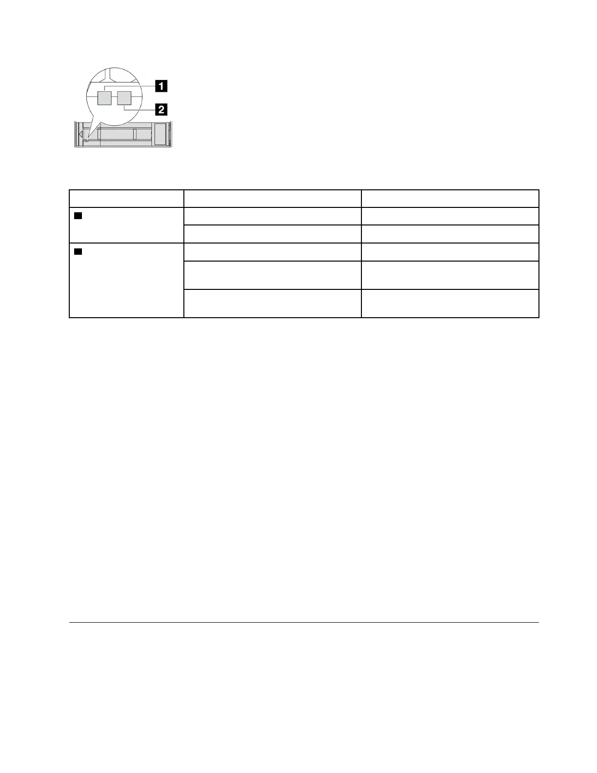
Figure 2. Drive LEDs
Drive LED
Status
Description
1 Drive activity LED (left) Solid green The drive is powered but not active.
Blinking green The drive is active.
2 Drive status LED (right) Solid yellow
The drive has an error.
Blinking yellow (blinking slowly, about one
flash per second)
The drive is being rebuilt.
Blinking yellow (blinking rapidly, about four
flashes per second)
The drive is being identified.
External diagnostics connector
The connector is for connecting an External Diagnostics Handset. For more about its functions, see
“External
diagnostics handset” on page 200
.
Front I/O module
The front I/O module provides controls, connectors, and LEDs. The front I/O module varies by model. For
more information, see
“Front I/O module” on page 15.
Pull-out information tab
The Lenovo XClarity Controller network access label is attached on the pull-out information tab. The default
Lenovo XClarity Controller hostname and the IPv6 Link Local Address (LLA) are provided on the tab.
For more information, see
Set the network connection for the Lenovo XClarity Controller.
Rack latches
If your server is installed in a rack, you can use the rack latches to help you slide the server out of the rack.
You also can use the rack latches and screws to secure the server in the rack so that the server cannot slide
out, especially in vibration-prone areas.
VGA connector
The VGA connectors on the front and rear of the server can be used to attach a high-performance monitor, a
direct-drive monitor, or other devices that use a VGA connector.
Front I/O module
The front I/O module provides controls, connectors and LEDs. The front I/O module varies by model.
Chapter 2. Server components 15