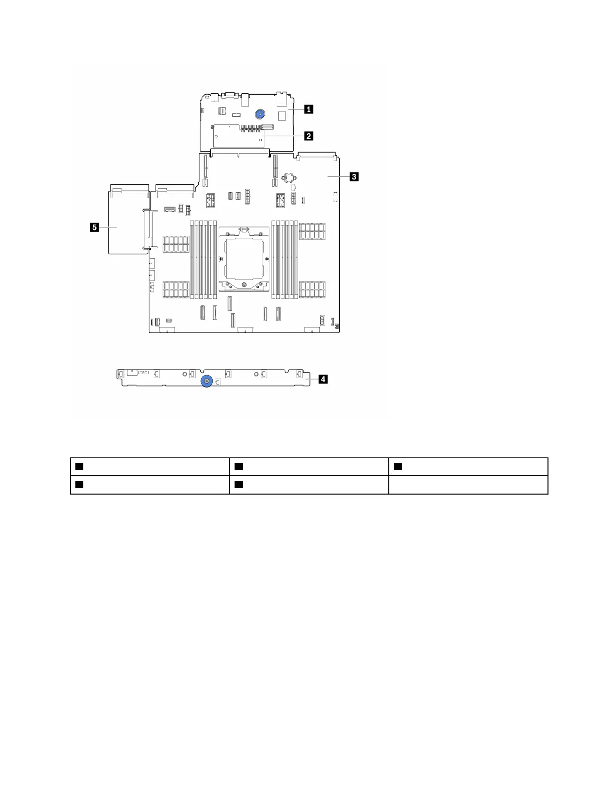
Figure 6. System-board-assembly layout
1 System I/O board
2 Firmware and RoT security module 3 Processor board
4 Fan board
5 Power inverter board (PIB)
For information about the LEDs that are available on the system board assembly, see:
•
“System-board-assembly LEDs” on page 209
• “LEDs on the firmware and RoT security module” on page 211
• “System-board-assembly connectors” on page 21
• “System-board-assembly switch” on page 23
System-board-assembly connectors
This section provides information about the internal connectors on the system board assembly that contains
the system I/O board and processor board.
Chapter 2. Server components 21