Backplanes: server models with 2.5-inch front drive bays
This section provides backplane cable connection information for server models with 2.5-inch front drive
bays.
Ensure below parts are removed before starting cable routing for front backplanes.
• Top cover (see
“Remove the top cover” on page 148)
• Air baffle (see
“Remove the air baffle” on page 50)
• Fan cage (see
“Remove the system fan cage” on page 146)
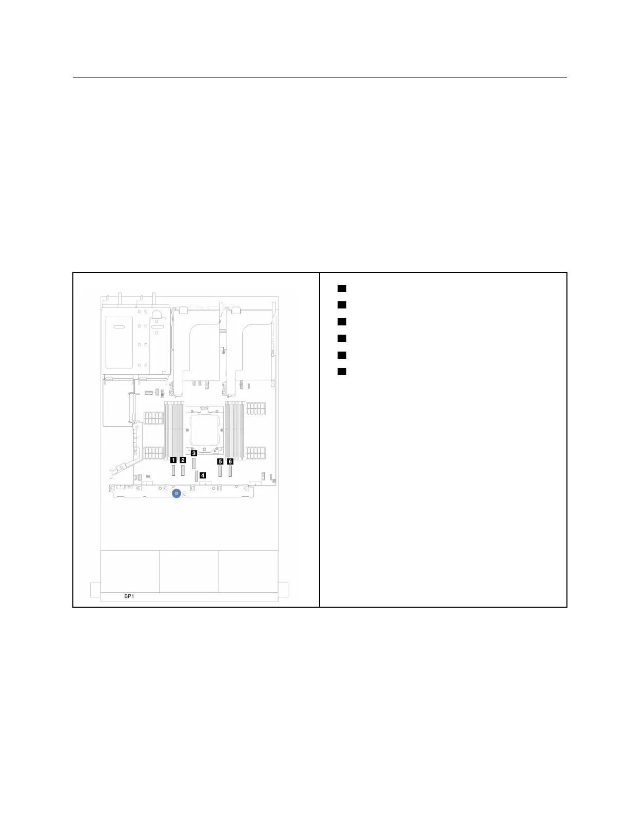
Notes: For the server with a performance heat sink (T-shape), remove the heat sink first before
disconnecting or connecting the cables which connect to PCIe 1, PCIe 2, PCIe 3, PCIe 4, PCIe 7, or PCIe 8
connectors (see the table below). After disconnecting or connecting the cables, install the heat sink back to
the server. See
“Remove a heat sink” on page 104 and “Install a heat sink” on page 109
• 1 PCIe 1 Connector
•
2 PCIe 2 Connector
•
3 PCIe 4 Connector
•
4 PCIe 3 Connector
•
5 PCIe 7 Connector
•
6 PCIe 8 Connector
Power cable connections
Connect the power cables for the front 2.5-inch drive backplanes as illustrated. Power cable connections are
the same for the following 8 x 2.5-inch front drive backplanes.
• 8 x 2.5-inch SAS/SATA backplane
• 8 x 2.5-inch AnyBay backplane
Chapter 6. Internal cable routing 163