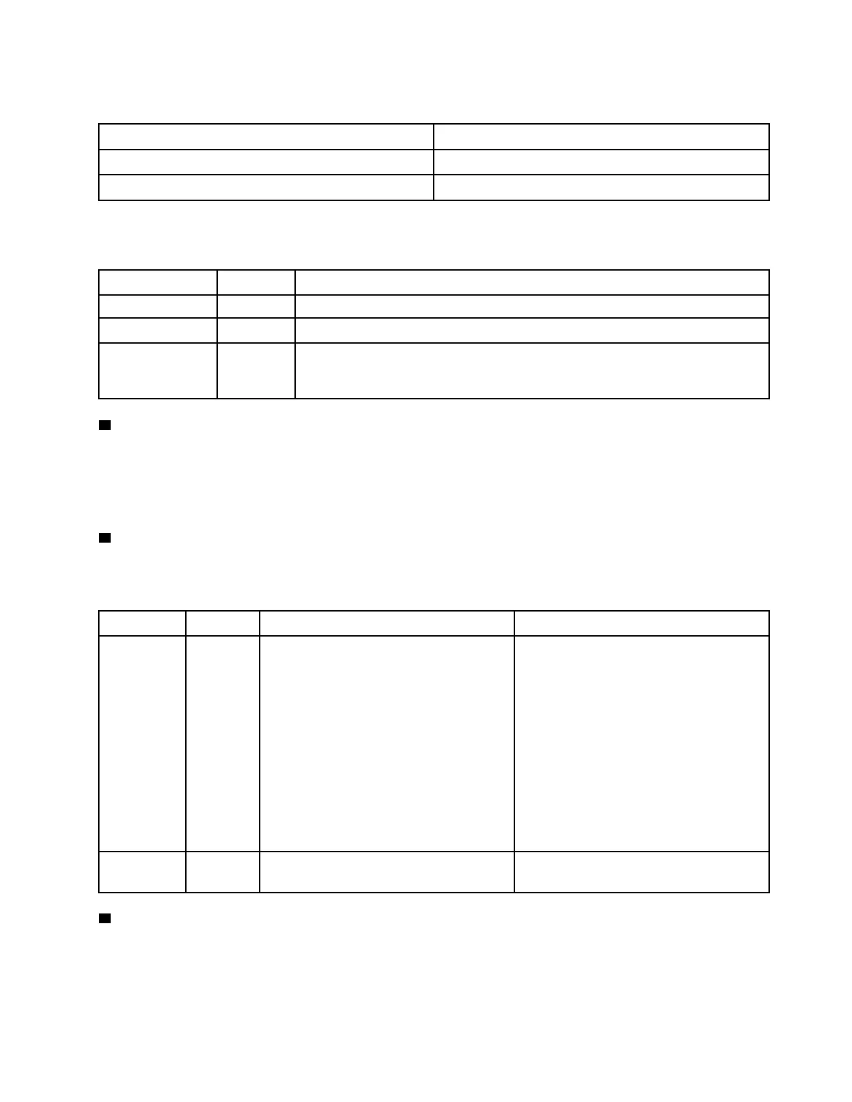
Compatibility of the NIC adapter and the network activity LED:
NIC adapter Network activity LED
OCP module Support
PCIe NIC adapter Not support
When an OCP module is installed, the network activity LED on the front I/O assembly helps you identify the
network connectivity and activity. If no OCP module is installed, this LED is off.
Status Color
Description
On Green
The server is connected to a network.
Blinking Green The network is connected and active.
Off
None The server is disconnected from the network.
Note: If the network activity LED is off when an OCP module is installed, check the
network ports in the rear of your server to determine which port is disconnected.
5 System ID button with system ID LED
Use this system ID button and the blue system ID LED to visually locate the server. Each time you press the
system ID button, the state of the system ID LED changes. The LED can be changed to on, blinking, or off.
You can also use the Lenovo XClarity Controller or a remote management program to change the state of the
system ID LED to assist in visually locating the server among other servers.
6 System error LED
The system error LED provides basic diagnostic functions for your server. If the system error LED is lit, one or
more LEDs elsewhere in the server might also be lit to direct you to the source of the error.
Status Color Description Action
On
Yellow An error has been detected on the server.
Causes might include but are not limited to
the following errors:
• A fan failure
• A memory error
• A storage failure
• A PCIe device failure
• A power supply failure
• A processor error
• A system I/O board or processor board
error
• Check the Lenovo XClarity Controller
event log and the system event log to
determine the exact cause of the error.
• Check if additional LEDs elsewhere in
the server are also lit that will direct you
to the source of the error. See
“Troubleshooting by system LEDs and
diagnostics display” on page 198
.
• Save the log if necessary.
Off
None The server is off, or the server is on and is
working correctly.
None.
7 Front operator panel
The front operator panel provides controls and LEDs, including the power button with power status LED,
network activity LED, system ID button with system ID LED, and system error LED.
Chapter 2. Server components 17
 Loading...


