D9U001ES2-0101_05122
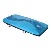
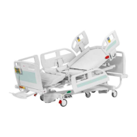
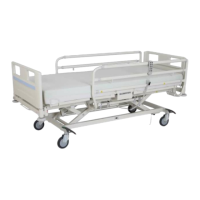
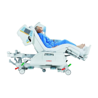
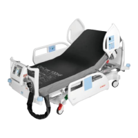
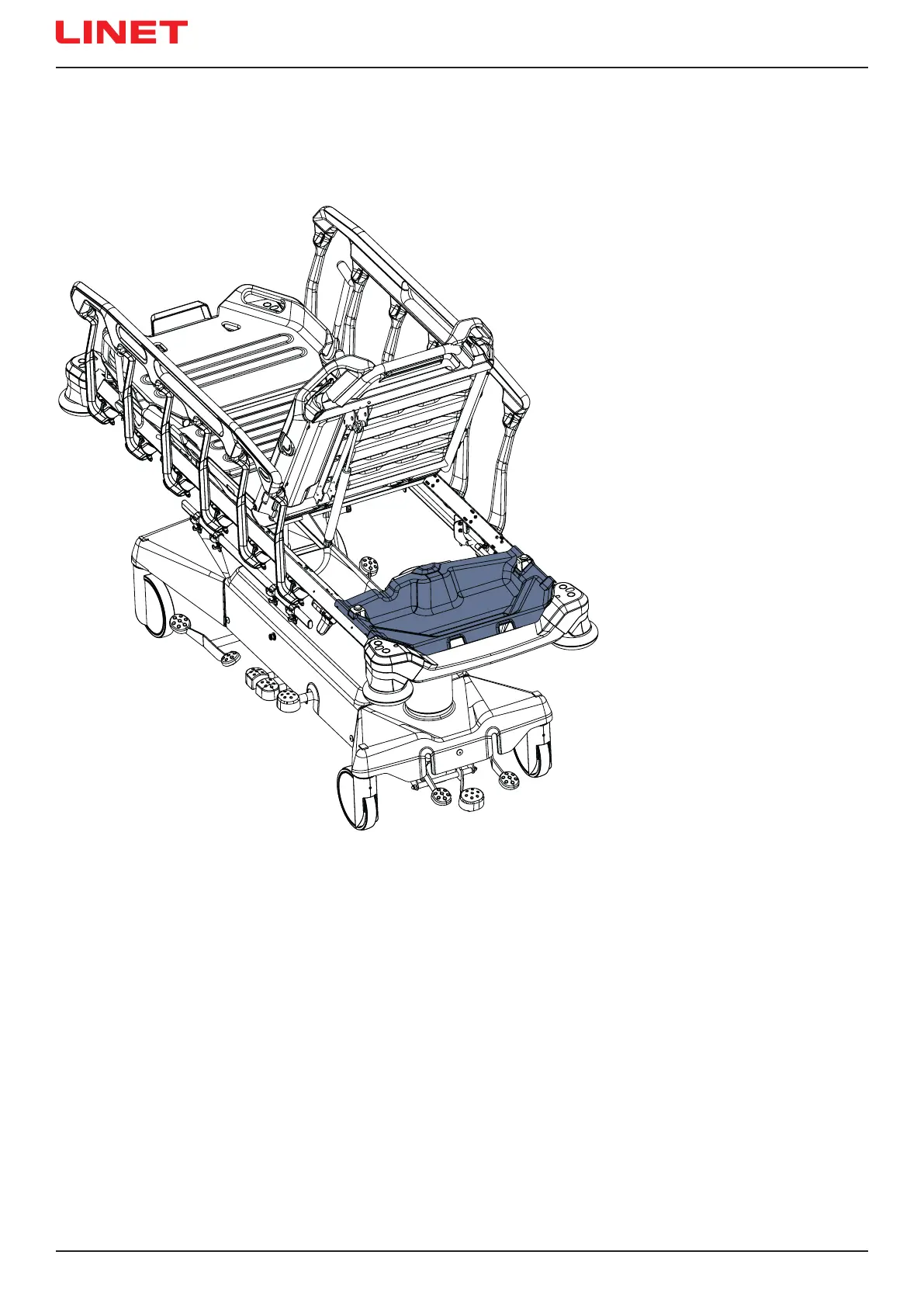
19.6 Storage Box
To clean the Storage Box:
► remove it from its place.
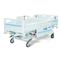
Storage Box is intended for patient´s things.
Storage Box is located under the Backrest.
Maximum load of the Storage Box is 10 kg.
Fig. Storage Box (under the Backrest)
 Loading...