D9U001ES2-0101_056
List of Figures
Fig. Example of Scales LW20 label ............................................................................................................................................. 14
Fig. Warning, read instructions for use ...................................................................................................................................... 14
Fig. Battery Activation Instructions ............................................................................................................................................ 15
Fig. Position of serial label on the Sprint 200 ............................................................................................................................ 18
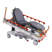
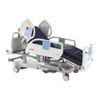
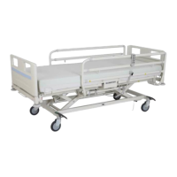
Fig. Stretcher Overview (Sprint 200 with 4-part Mattress Support Platform) .......................................................................... 28
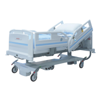
Fig. Stretcher Overview (Sprint 200 with 2-part Mattress Support Platform) .......................................................................... 29
Fig. 4-part Mattress Support Platform ........................................................................................................................................ 39
Fig. 2-part Mattress Support Platform ........................................................................................................................................ 39
Fig. Instructions to remove the plastic mattress support platform covers ............................................................................. 40
Fig. Instructions to insert the plastic mattress support platform covers ................................................................................ 41
Fig. Eight Patient Restraint Points (4-part mattress support platform) ................................................................................... 42
Fig. Potential equalisation - male (head end, bottom view) ...................................................................................................... 43
Fig. Potential equalisation connector - female .......................................................................................................................... 43
Fig. Power Supply Cord on the head end of the Sprint 200 with scales or with i-Drive Power ............................................. 46
Fig. Hook for hanging Power Supply Cord ................................................................................................................................. 46
Fig. Power Supply Cord leading from the undercarriage cover and wound around the Accessory Rail ............................. 47
Fig. Position of the Battery Box under the Seat Section of Sprint 200 with scales ............................................................... 49
Fig. Battery Box with Battery Isolating Foil under the Seat Section (bottom view) ............................................................... 50
Fig. Tipping the Battery Box Holder out (bottom view) ............................................................................................................. 52
Fig. Fixation of the Battery Box under the Seat Section (view from Foot End) ...................................................................... 52
Fig. Battery Box with Cover xed with 4 screws ....................................................................................................................... 53
Fig. Opened Battery Box with 4 batteries ................................................................................................................................... 53
Fig. Manipulation with Collapsible Siderail ................................................................................................................................ 56
Fig. Positions of both Siderail Release Levers when the siderail is locked ........................................................................... 57
Fig. Positions of both Siderail Release Levers when the siderail is unlocked ....................................................................... 57
Fig. Release of the siderail at head end and foot end ............................................................................................................... 58
Fig. Three Pedal Positions (Green Drive Pedal) ......................................................................................................................... 59
Fig. Positions of Brake pedals ..................................................................................................................................................... 60
Fig. Positions of Drive pedals ...................................................................................................................................................... 60
Fig. Manipulation with Backrest Release Handle ...................................................................................................................... 62
Fig. Positions of Backrest Release Handles .............................................................................................................................. 62
Fig. Position of Thighrest Latch .................................................................................................................................................. 64
Fig. Calfrest Positioning ............................................................................................................................................................... 66
Fig. Catch in the ratchet-bar ........................................................................................................................................................ 66
Fig. Positions of Lifting pedals .................................................................................................................................................... 67
Fig. Positions of Head End Lowering pedals and Foot End Lowering pedals ........................................................................ 68
Fig. Positions of Head End Lowering pedals ............................................................................................................................. 70
Fig. Position of Head End Trendelenburg Pedal (optional)....................................................................................................... 70
Fig. Positions of Foot End Lowering pedals .............................................................................................................................. 71
Fig. Preparation for Cardiopulmonary Resuscitation (2-part Mattress Support Platform) .................................................... 73
Fig. Preparation for Cardiopulmonary Resuscitation (4-part Mattress Support Platform) .................................................... 74
Fig. Scales and Bed Exit Alarm Monitoring Control Panel (keyboard and display) ............................................................... 75
Fig. Display description (scales) ................................................................................................................................................. 76
Fig. Discrete Mode ........................................................................................................................................................................ 76
Fig. Sprint 200 with scales is overloaded (pop-up) ................................................................................................................... 78
Fig. Scales and Bed Exit Alarm Monitoring Control Panel (keyboard and display) ............................................................... 81
Fig. Display description (Bed Exit Alarm Monitoring) ............................................................................................................... 82
Fig. Bed Exit Alarm Monitoring Button with 2 Green Indicators above ................................................................................... 83
Fig. Visual signalisation of the Bed Exit Alarm on the display (yellow eld and black symbols) ......................................... 84
Fig. Two pictures alternating during triggered Bed Exit Alarm ................................................................................................ 84
Fig. Settings Menu ........................................................................................................................................................................ 86
Fig. Verication Screen ................................................................................................................................................................ 86
Fig. Software and Hardware Versions Screen ............................................................................................................................ 86
Fig. Settings Menu (TIME AND DATE) ......................................................................................................................................... 87
Fig. TIME AND DATE Menu........................................................................................................................................................... 87
Fig. Settings Menu (TIME DATE SETTING) ................................................................................................................................. 88
Fig. TIME DATE SETTING Menu ................................................................................................................................................... 88
Fig. Accessory Rail with plastic hooks (on side) ....................................................................................................................... 90
Fig. Accessory Rail with plastic hooks (at head end) ............................................................................................................... 90
Fig. DIN Rail (on side) ................................................................................................................................................................... 91
Fig. Urinary Bag Holder (on side) ................................................................................................................................................ 91
Fig. Storage space (Undercarriage Cover of the Sprint 200 with i-Drive Power) .................................................................... 92
Fig. Storage space (Undercarriage Cover of the Sprint 200 without i-Drive Power) .............................................................. 92
Fig. Fixation of an oxygen bottle on the undercarriage cover with straps for oxygen bottles ............................................. 93
Fig. Activation of Fifth castor ...................................................................................................................................................... 94
Fig. Pair of Foldable infusion stands (head end) ....................................................................................................................... 95
 Loading...