DLP-513: Detailed Level Procedure 363-206-285
Page 4 of 20 Issue 2, February 2000
DDM-2000 OC-3 MULTIPLEXER
NOTE:
To set switch to ON, depress rocker or slide switch toward side labeled
ON in the figure. To set switch to OFF, depress rocker or slide switch
toward side labeled OFF in the figure.
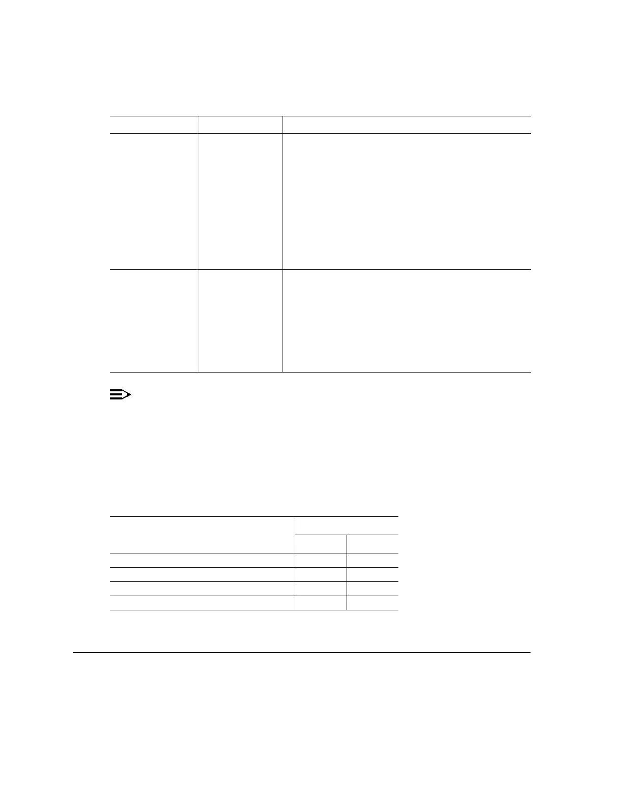
Determine the timing mode from work order or office records. Refer to Table C
and Figure 2 and set the timing mode as required for the TGS circuit pack(s).
* If an invalid setting is selected, FAULT LED is lighted and an alarm is generated
unexpected CP type or unexpected CP switches)
External - Mult External - Mult This topology is used when both NE’s have access to and
are receiving its timing from BITS clocks. The
recommendation is to have these BITS synchronized to
references which are traceable to the same PRS. If these
guidelines are followed the subnetwork created by these
two NE’s would be operating synchronously. Note:
DDM-2000 systems are designed to operate in
pleisiochronous timing topologies. The DS1 output
generated by each NE is regenerated from the input DS1
timing reference and could be used to distribute this
reference to other shelves colocated in the same bay to
conserve ports on the BITS.
Line Timing Line Timing Caution! This topology creates a timing loop and it is not
supported. The NE with access to an external timing
reference traceable to a PRS, if available, should be
provisioned for External - Mult. If the reference available is
an optical reference provision to Line Timing with the
proper source using the set-sync command. If automatic
synchronization reconfiguration is supported and enabled
in a system, both NEs will attempt to switch to another line
timing source, if available, to prevent a timing loop.
Table C – BBF2 TGS Timing Mode Switch Setting
Timing Mode
Switch S1 Settings
S1-3 S1-4
Free Running ON ON
DS1 External, MULT Mode OFF ON
Line Timed ON OFF
Invalid* OFF OFF
Table B – BBF2 TGS Synchronization Provisioning Topologies (Contd)
NE 1 NE 2 Application Comments