DLP-523: Detailed Level Procedure 363-206-285
Page 7 of 30 Issue 2, February 2000
DDM-2000 OC-3 MULTIPLEXER
9.
NOTE:
Switches S1-1 and S1-2 were ignored by the system the first time the
TGS was installed unless the timing mode was set to
DS1 External
.
Subsequent removal or replacement of the TGS requires that switches
S1-1 and S1-2 be set the same as the original settings or an update upd
must be performed.
Is timing mode set to
DS1 External
?
If YES, then continue with Step 10.
If NO, then proceed to Step 11.
10. Refer to Table D and Figure 1 and set the DS1 line coding and frame format as
required for the TGS circuit pack.
11.
!
CAUTION:
When all OC-3 shelves in a bay are timed from a common external timing
supply, removal of the bottom shelf
TGS
circuit pack will cause a
momentary transmission hit on all shelves in the bay.
NOTE:
A TGS circuit pack is required in TIMING slot 1 to protect against
accidentally downloading wrong software and interrupting transmission.
Transmission configuration information is stored in the TGS circuit pack in
TIMING slot 1. During software download procedures the software
checks the information stored in the TGS 1 circuit pack. If the information
is incompatible with the controller software information, an alarm is
generated.
NOTE:
If a signal has previously been applied to the original TGS circuit pack,
the FAULT lamp will flash when the new TGS is installed until the signal
tests good.
Remove old TGS and install replacement TGS.
Response: FAULT LED on the TGS lights (flashes) for about 15
seconds and then goes off.
12. STOP. YOU HAVE COMPLETED THIS PROCEDURE.
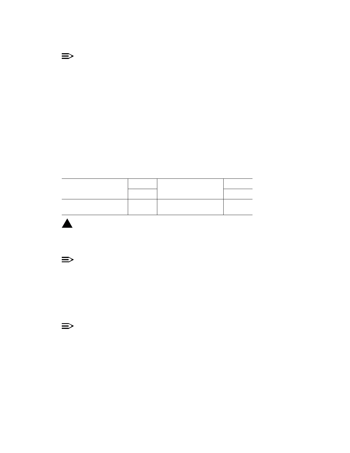
Table D – TGS DS1 Line Coding and Frame Format Switch Settings
DS1 Line Code
Switch
DS1 Frame Format
Switch
S1-1 S1-2
AMI ON SF ON
B8ZSOFFESF OFF