4-71
TMS9000-2 OPERATOR MANUAL OPERATING PROCEDURES
Published 02-21-2019, Control # 611-05
extending the boom. The telescoping arrow to the
left is always retracting the boom.
When a boom section is first unlocked, the boom
section may automatically extend 50 mm (2
inches). The operator must be aware of this motion
and have the crane in a position to anticipate this
motion.
NOTE:
• Switch on the telescoping mechanism, refer to
Telescoping mechanism, page 4-60.
• Open the Telescoping semi-automation menu (1,
Figure 4-138).
Semi-auto Mode
Introduction
The Semi-auto Mode is typically the standard method for
telescoping the pinned boom.
It is important to understand that a pinned boom has a
telescoping cylinder that can disconnect and reconnect
(unlock/lock) to boom sections, as well as disconnect and
connect (unlock/lock) boom sections to each other. This is
accomplished by a pinning mechanism or pinning “head” at
the near end of the barrel of the telescoping cylinder (the rod
is fixed to the base section and the barrel extends within the
boom). This pinning mechanism has a set of sensors and an
electronic module to communicate with the crane control
system. Using these sensors, as well as a precision length
sensor for the location of the telescoping cylinder within the
boom, the crane control system commands the pinning
mechanism to perform the locking operations. The Semi-
auto Mode is the simplest approach to operating the pinned
boom, since it automatically handles the most complicated
aspects of the pinning.
It is important to realize that the control system is performing
automated motions within the boom at some points in the
telescoping process. At other times the operator is able to
move the boom components. Then the automated motions
can occur once again after the operator has indicated the
appropriate next action for telescoping the boom.
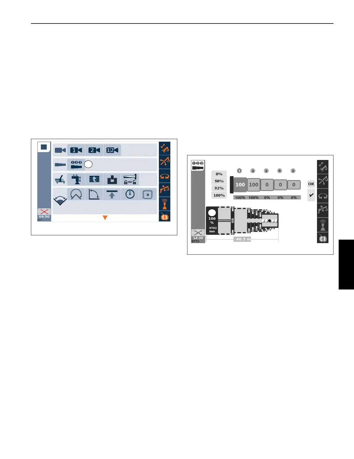
The Semi-auto screen of the operating display (refer to
Figure 4-139) shows a graphic schematic near the bottom of
the screen that indicates the current status of the boom
computed by the control system (however the operator must
continue to monitor the status of the physical boom to
compare with this schematic). In Figure 4-139, there is a
100% (1) shown for the position of the telescoping cylinder
(above the 9703 mm distance value). The graphical
representation of the telescoping cylinder rod protrudes
horizontally from the left end of the schematic (near item 1).
The end of the graphical representation of the rod at the T1
boom section which is at the 100% pinning location. The
slightly larger rectangular entity at the right end of the
telescoping cylinder rod represents the pinning mechanism.
The example in Figure 4-139 shows the value of 9703 mm
for the extension of the telescoping cylinder within the boom.
This is the value from the precision length sensor. The
example also shows a value of 40.5 meters as the overall
boom length. The example shows the T2 boom section had
been previously extended and locked at its 100% pinning
location. The remaining boom sections are locked at their
0% pinning location (and they were all extended as the T2
boom section extended).
As mentioned earlier, there are times when the control
system is performing automated motions. The example in
Figure 4-139 shows some dots at the end of the schematic
graphic. These dots, as well as the one dark dot cycling back
and forth to the left and right, indicates that automated
motions are occurring.
Figure 4-140 shows the same screen when the operator is
able to control motions of the boom sections. In this case,
there is a left and/or right pointing arrow (instead of the dots
shown in Figure 4-139). As is consistent with the schematic's
orientation, the left arrow indicates retracting the boom, the
right arrow indicates extending the boom. The control device
(typically the joystick in the standard joystick option) would
 Loading...


