OPERATING PROCEDURES TMS9000-2 OPERATOR MANUAL
4-88
Published 02-21-2019, Control # 611-05
locking pin into the telescopic section and thus unlocks the
section.
The screw is screwed out again to lock the section manually.
The main boom is designed in such a way that the locks can
be operated in emergency mode from the outside for most
fixed lengths.
NOTE: If the telescoping cylinder is in the foot section of a
telescopic section, this telescopic section cannot
be locked or unlocked manually.
Prerequisites
The following prerequisites must be fulfilled before unlocking
a telescopic section manually:
• The telescopic section to be unlocked is attached to an
auxiliary crane with sufficient load bearing capacity and,
in this way, is secured against independent retraction.
Or
• The main boom is lowered into a horizontal position so
that the telescopic section is unable to retract
independently.
Maintenance
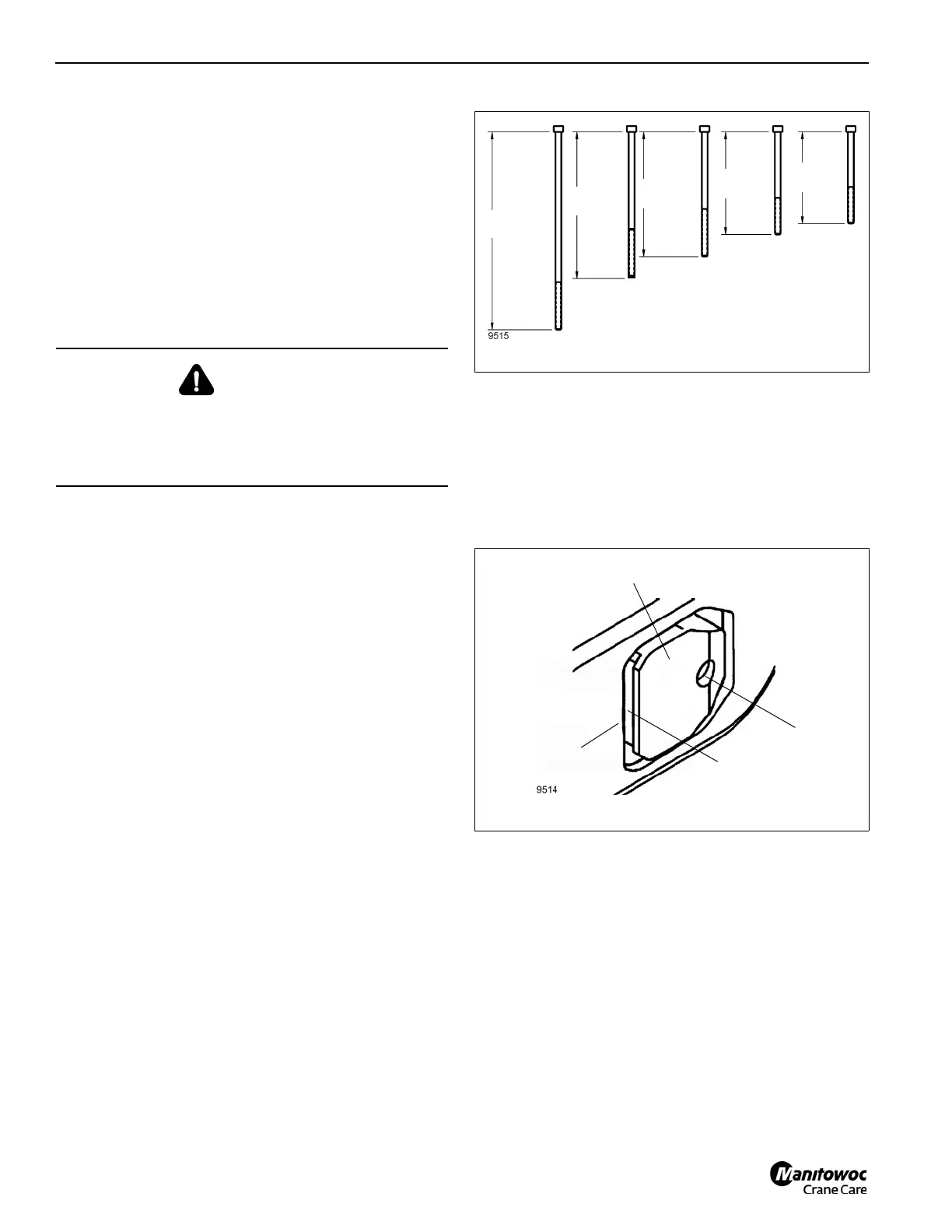
For manual unlocking, two screws are supplied for each
telescopic section (Figure 4-192),
• 125 mm (4.92 in) length for telescopic section 5.
• 140 mm (5.51 in) length for telescopic section 4.
• 170 mm (6.69 in) length for telescopic section 3.
• 200 mm (7.87 in) length for telescopic section 2.
• 270 mm (10.63 in) length for telescopic section 1.
You can only lock or unlock a telescopic section manually if
the recess (2, Figure 4-193) in the locking pin(1) no longer
engages in the telescopic section (3) above it.
Extend the telescopic section approximately 20 mm (0.79 in)
(with an auxiliary crane, forklift or other means of external
force). The locking pin (1) must be centered in the opening
and the recess (2) may no longer engage in the telescopic
section (3) above it.
Unlocking Telescopic Sections
When unlocking sections start with Tele 5 (fly) and work your
way in towards Tele 1 as far as possible. Unlock and lock
only one section at a time.
1. Remove the grease fitting from the bore hole (4,
Figure 4-193).
2. Insert a screw into the hole (4). The locking pin (1) is
retracted in the process. You can assist this process by
lightly hammering on the locking pins.
3. Tighten the screw against the spring load until the
locking pin (1) is pulled in as far as it will go and is
situated behind the side wall of the telescopic section.
WARNING
Risk of crushing from retracting boom!
Failure to follow these prerequisites could allow a boom
section to retract uncontrolled resulting in injury or
equipment damage.
270 mm
(10.63 in)
9515
Tele 5
Tele 4
Tele 3
Tele 2
Tele 1
200 mm
(7.87 in)
170 mm
(6.69 in)
140 mm
(5.51 in)
125 mm
(4.92 in)
FIGURE 4-192
 Loading...


