Grove Published 02-21-2019, Control # 611-05 3-111
TMS9000-2 OPERATOR MANUAL OPERATING CONTROLS AND INDICATORS
Display Components
Table 3-4 Display Components
5 Function Selector Buttons (qty 10)
Momentary buttons that activate the selected function in the display:
5a - Outrigger beams
5b - Outrigger jacks
5c - Boom lift
5d - Option: luffing boom extension, boom extension assist, counterweight
5e - Horn (activates the superstructure horn)
5f - Escape: exits the selected function screen
5g - Information (software version/revision and crane serial number)
5h - Engine
5i - Swing
5j - Main/aux hoist
6
7
Left Motion Button
Right Motion Button
Holding down either button operates the selected function in the desired
direction (for example: turn a drum up or down, extend or retract a jack or
beam, swing right or left, engage or disengage a pin).
Speed depends on how far either button is depressed.
8 Left Enable Button
Holding down either button allows (enables) a selected function to be
operated in the desired direction by the corresponding motion button.
9 Right Enable Button
10 Battery 3.2Ah Lithium-Po rechargeable battery
11 E-Stop Knob
Pull out = allow operation of the crane functions from the remote control
Push in = STOP engine and current function
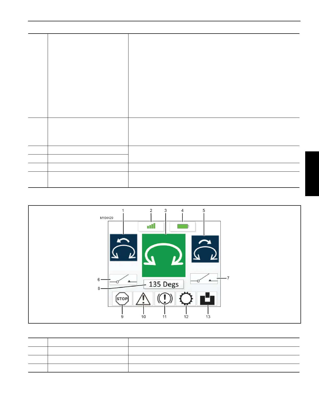
Item Component (Figure 3-169) Description
1 Left Motion Command Depicts the operation that is controlled by the left motion command button
2 Transmission Strength More bars = greater strength, and vice versa
3 Function Screen Depicts the function that is being operated (swing in this example)
 Loading...


