OPERATING CONTROLS AND INDICATORS TMS9000-2 OPERATOR MANUAL
3-140 Published 02-21-2019, Control # 611-05
disabled when shipped from the factory. Once enabled, the
system stays enabled until disabled through the ODM.
NOTE: ECO mode stays disabled (or enabled)
independent of ignition key cycles and disconnect
switch cycles.
When enabled the throttle setpoint will be set to the ECO
mode throttle percent setpoint unless the operator had
previously set it to a higher value using the Increment /
Decrement switch.
The operator can increase the throttle command using the
throttle pedal independent if ECO mode is active or inactive.
ECO mode is forced to inactive when the crane's
transmission is being shifted to Forward or Reverse, or all
crane functions are enabled.
When active, ECO mode will ramp the throttle percent from 0
to setpoint when any crane function command goes above
5% command. Once ECO mode’s output is at the setpoint,
the output will stay at the setpoint until no crane functions are
being commanded for the set time interval. Then the ECO
mode's throttle command is to be set to 0% (step down).
NOTE: Ramp time for increasing throttle percent is 2
seconds from 0% to 100% throttle (slope = 50% per
second).
Operation
• Crane is able to idle at 600 RPM when crane functions
are not enabled.
• Crane idles at 800 RPM when any crane function has
been enabled.
• When user turns ECO mode ON:
- Crane ramps engine from idle to operating RPM
using the first 15% of the joystick movement to
control the ramp.
- Crane maintains operating RPM while crane
functions are active and for a set period of time after
crane functions go inactive.
- Crane ramps engine speed back down to idle point.
Benefits
• Less noise and less fuel consumption versus
maintaining crane at fixed “operating RPM”.
• Set point for engine operating speed is easily changed
by the user.
• User can command additional engine speed at any time
using the accelerator pedal.
• Lower idle speed is better for “creep speed” driving, and
improves braking performance.
ELECTRICAL SYSTEM
Voltage monitoring warning
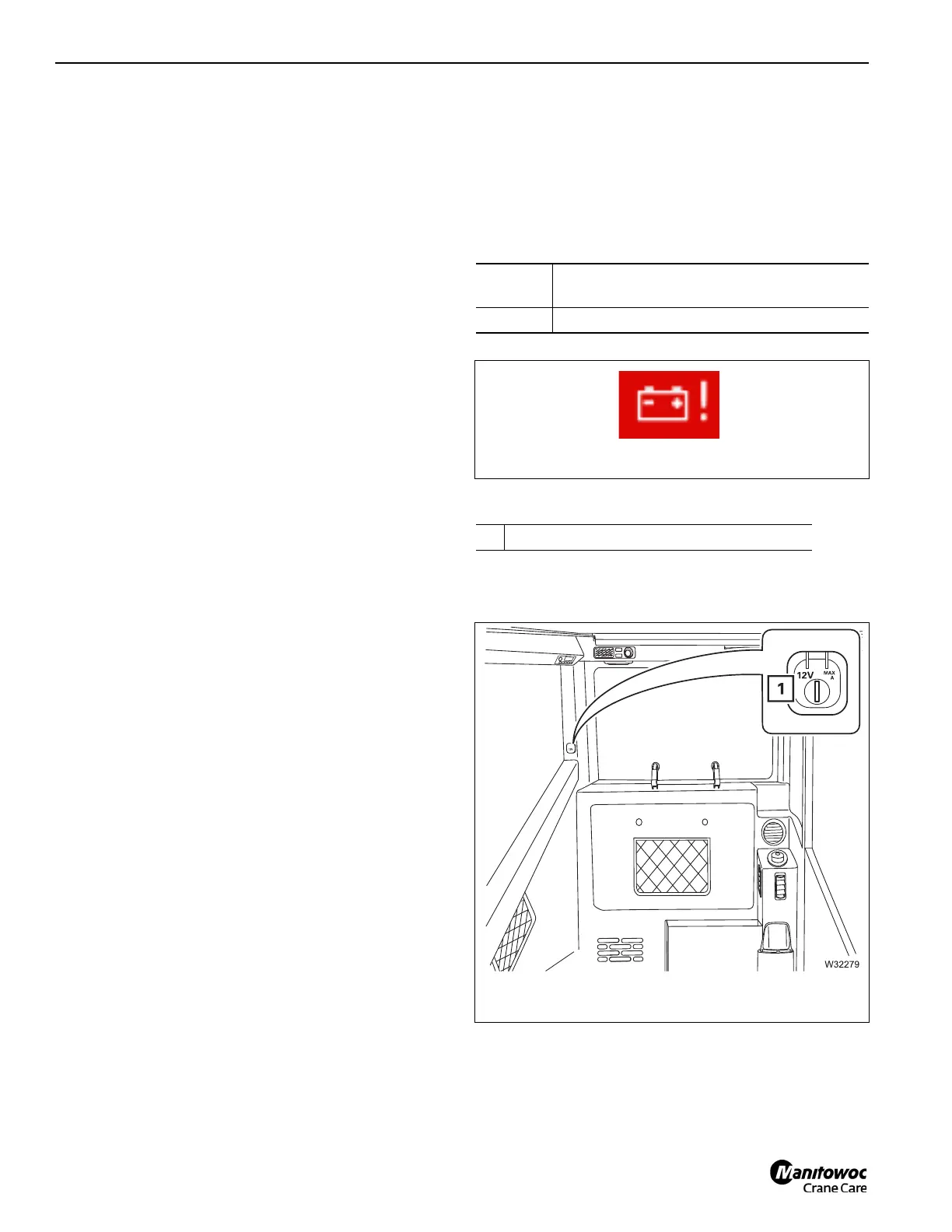
Sockets 12 V
Only connect electrical devices with the matching
specification to the socket (Figure 3-218).
Display
symbol:
Engine on – power failure – switch off engine
(Figure 3-217)
Off: Engine on – no fault
1 Socket 12 V/max. 10 A

 Loading...


