4-93
TMS9000-2 OPERATOR MANUAL OPERATING PROCEDURES
Published 02-21-2019, Control # 611-05
14. Install flags and oversize load placards as required.
Travel Precautions
NOTE: The following paragraphs list several important
travel precautions which must be taken into
consideration when traveling with the crane in the
trailing boom configuration.
• Use of the trailing boom feature may require reducing
travel speeds. Adjust travel speed to suit driving
conditions (i.e. traffic, highway, weather).
• The crane boom and trailer combination requires a wide
turning radius. When turning during driving, allow extra
space on both the left and right sides of the carrier.
• The superstructure will rotate and stick out past the side
of the carrier that is opposite the direction the carrier is
being steered/turned when traveling.
• Reduce travel speed to avoid undesired weight transfer
between the carrier and the boom trailer at abrupt crests
and undulating terrain.
Returning to Normal Crane Operation
1. Position the crane and trailing boom carrier on a firm
level surface with the boom carrier directly behind the
crane.
2. Block the wheels and apply the parking brakes.
3. Turn the lift cylinder float valves clockwise to the
normally closed position.
4. Pull out the knobs on the swing brakes to set for normal
brake operation and padlock.
5. Turn air locking pin valve knob to the RETRACT
position. Visually check locking pins to ensure they are
disengaged.
6. Raise the boom from the trailing boom carrier.
7. Disconnect all air and electrical lines from the rear of the
crane.
Parking the Trailing Boom Carrier
Use the following procedure when parking the trailing boom
carrier.
1. Apply the emergency/parking brake in the carrier cab.
Refer to Trailing Boom Trailer Emergency Brake Control
(Optional), page 3-8.
2. Chock the tires on the trailing boom carrier.
NOTE: The trailing boom carrier brakes are air pressure
applied and may bleed off.
3. Disconnect the boom from the trailing boom carrier as
described under Returning to Normal Crane Operation.
TILT-UP PANEL PROCEDURE USING THE
HEAVY DUTY BOOM EXTENSION
Refer to Installing Manually Offsetable Heavy Duty Boom
Extension, page 6-82, Tilt-Up Panel Lifting, page 2-22, in the
Safety Information section for more information.
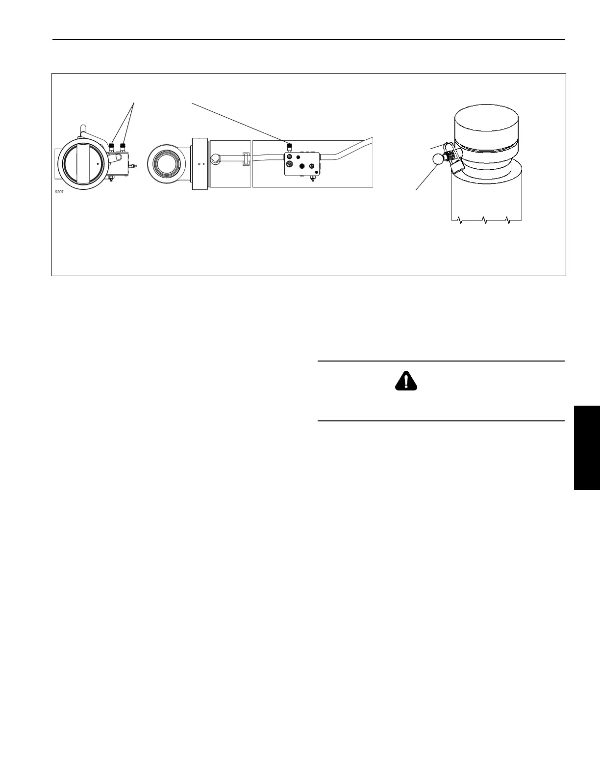
7140-4
Swing Brake Release for Trailing Boom
Padlock
(Pulled Out)
Brake Set for
Normal Operation
(Push In) Brake
Set for Trailing
Boom
FIGURE 4-199
9207
Lift Cylinder
Float Valves
WARNING
The superstructure is free to swing when the trailing boom
swing brake release valve is released.

 Loading...


