OPERATING PROCEDURES TMS9000-2 OPERATOR MANUAL
4-84
Published 02-21-2019, Control # 611-05
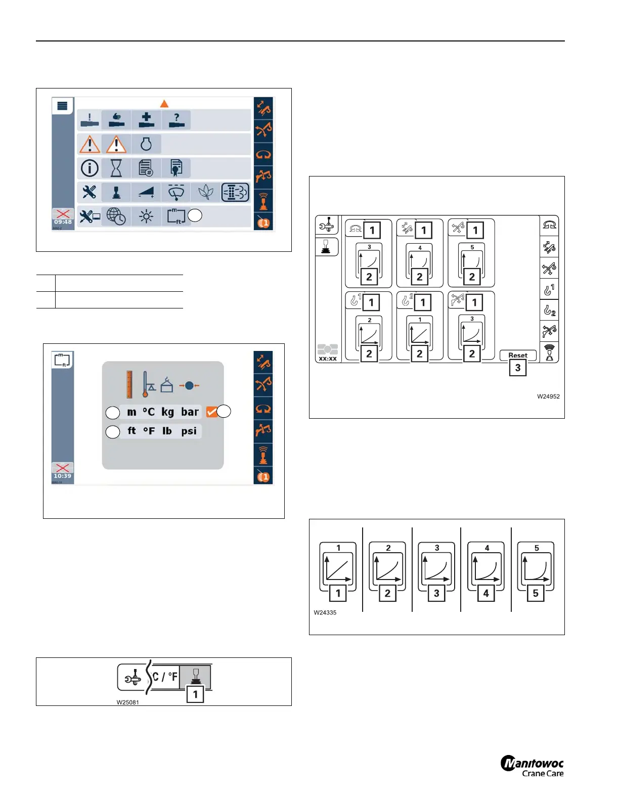
• Open the Switch units menu (1, Figure 4-172).
• Select and confirm the symbol (Figure 4-173):
The symbol (3) shows the respective confirmed selection.
Setting the characteristic curves for the
control levers
The control lever characteristic curve determines how high
the power unit speed should be for a particular control lever
movement.
You can assign different control lever characteristic curves to
the power units.
Open the Settings (1, Figure 4-174) menu.
The symbols (2, Figure 4-175) show the set characteristic
curves of the power units (1).
• Select the power unit for which you would like to change
the characteristic curve.
• Set the desired characteristic curve.
Select and confirm symbol (3) to reset all power units to
characteristic curve 1.
There are five characteristic curves:
The higher the number of the characteristic curve, (1,
Figure 4-176) to (5), the further the control lever must be
moved to get a clear increase in speed.
With characteristic curve (5), you can work particularly
sensitively with the control lever.
When default characteristic curves are not used, the icon
shown in Figure 4-177 will be shown in the left margin of the
operating display (ODM).
1 To display metric units
2 To display imperial units

 Loading...


