GROVE 6-63
TMS9000-2 OPERATOR MANUAL SET-UP AND INSTALLATION
Published 02-21-2019, Control # 611-05
Mechanical Luffing Boom Extension
(Adjustable Boom Extension)
Extension Angle Adjusting Mechanism
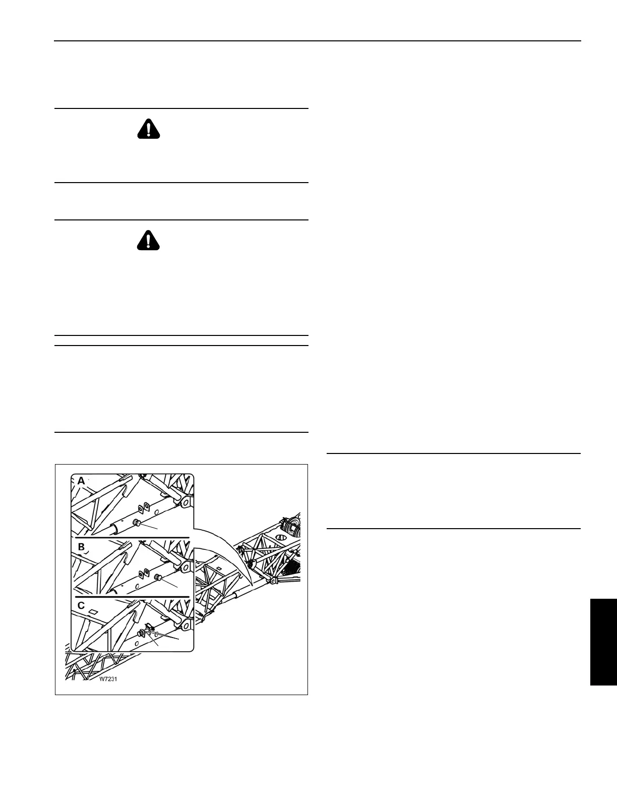
Refer to Figure 6-124.
The boom extension angle is determined by the position of
the adjusting pin. There are three positions:
•0° angle: (A) – For a 0° angle, the pin (1) is installed in
the front location and is secured with the retaining clip.
• 20° angle: (B) – For a 20° angle, the pin (1) is installed in
the rear location and is secured with the retaining clip.
• 45° angle: (C) – For a 45° angle, the pin (1) is removed
and stored in the holder (2) and secured with the
retaining clip.
Setting the Offset Angle with an Auxiliary Crane
NOTE: The information in this section only applies to the
mechanical luffing boom extension.
1. Lift the extension with the auxiliary crane until the pin (1)
(Figure 6-124) is relieved of load.
2. Lift or lower the extension with the auxiliary crane until
the adjusting pin can be installed into the position for the
required angle, refer to Extension Angle Adjusting
Mechanism, page 6-63.
3. Lower the extension with the auxiliary crane and remove
the lifting gear.
If the lattice extension now touches the ground at the
current angle, the angle will set itself when the main
boom is raised.
Setting the Offset Angle without an Auxiliary Crane
If an auxiliary crane is not available, the extension head must
rest on the ground before the angle is changed.
Entering the RCL Code
Enter the RCL rigging code for the boom extension offset
angle in accordance with the current rigging mode of the
crane, refer to the Load Chart, Chapter Remarks.
When adjusting the angle without an auxiliary crane, you
must enter an RCL rigging code. The RCL rigging code
depends on:
• the rigged outrigger span
• the rigged counterweight
• the working position.
The superstructure must be in a working position permitted
by the Load Chart for the RCL rigging code that was entered.
DANGER
Crushing Hazard!
During installation and removal, always use the proper
equipment with sufficient load bearing capacities.
WARNING
Crushing Hazard!
Uncontrolled movement of the boom extension can result
in death or serious injury. The Boom extension must be
supported before removing the adjusting pins.
Support the extension with an assist crane or set the tip of
the extension on the ground before adjusting the angle.
CAUTION
Machine Damage!
The deflection sheave must be stowed before adjusting
the offset angle of the extension. Failure to stow the
deflection sheave may result in damage to the extension
or sheave.
W7231
FIGURE 6-124
1
2
1
1
- 45°
- 0°
- 20°
CAUTION
Rope Damage!
The hoist cable can be damaged if it is reeved while the
extension nose is on the ground. Unreeve the hoist cable
from the extension nose before adjusting the offset angle.

 Loading...


