SET-UP AND INSTALLATION TMS9000-2 OPERATOR MANUAL
6-20
Published 02-21-2019, Control # 611-05
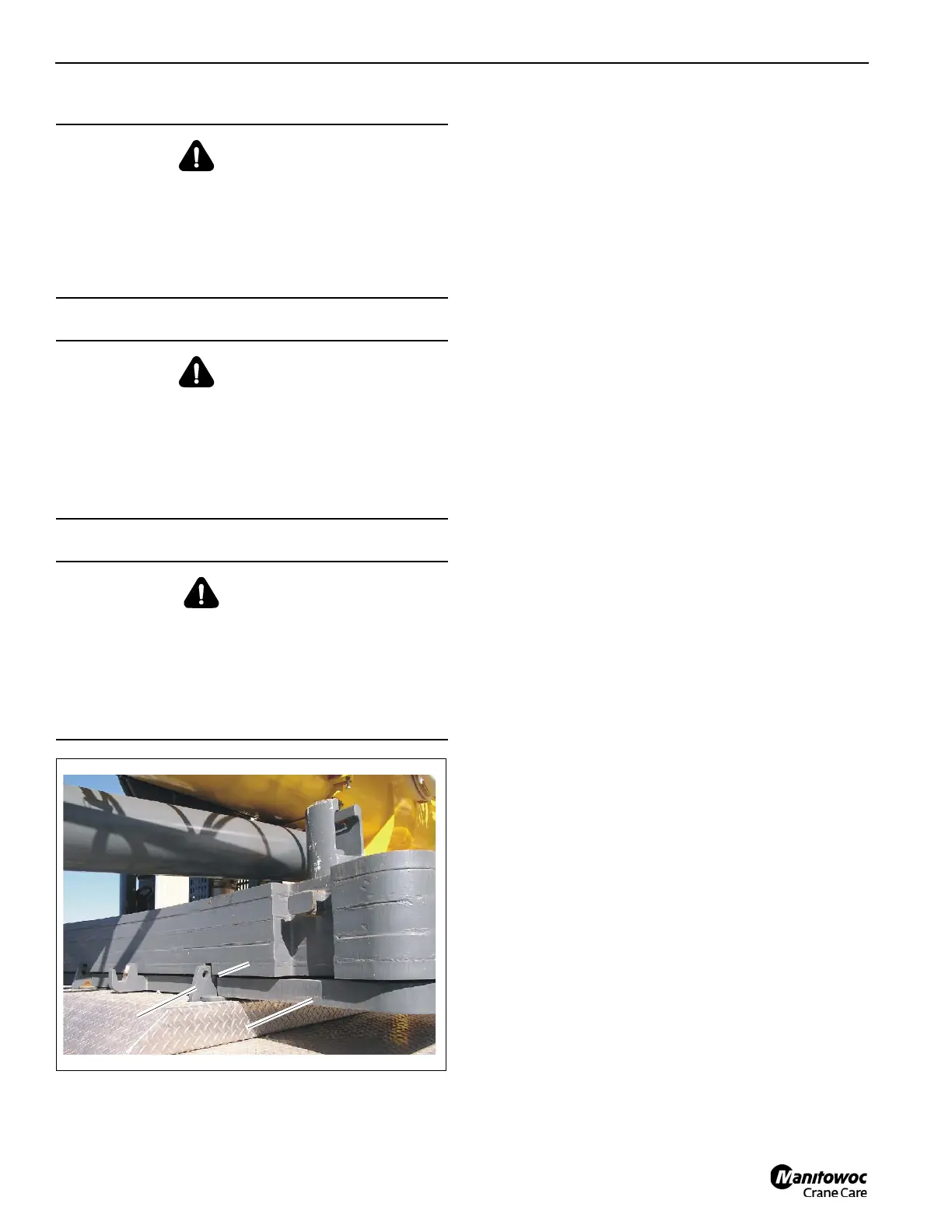
On the counterweight platform there are four retaining
brackets (1, Figure 6-24), which brings the 3,000 lb tray plate
(3) into proper position for rigging and for secure driving.
1. Sling the 3,000 lb tray plate and lift it onto the
counterweight platform.
2. Position the 3,000 lb tray plate (3) in such a way that the
four retaining brackets (1) fit into the four cut outs (2).
Check the position of the locking pins for
3000 and 5,000 lb
counterweight sections
There are three counterweight sections that require locking
pins during rigging; the 3000 lb counterweight plate and the
two 5000 lb counterweight plates, The locking pins allow the
3000 lb and 5000 lb counterweight sections to be assembled
and secured together. Care must be taken to ensure that the
locking pins are in the proper positions during rigging work.
The crane can travel on the highway with up to a maximum
of 16,000 lbs. attached to the superstructure.
Ensure all the locking pins are in the Locked position when:
• lifting the 3000 lb and/or the 5000 lb counterweight
sections onto and off of the crane.
• raising and lowering the counterweight assemblies with
the counterweight hoisting unit.
• swinging the turntable with the counterweight attached.
• traveling with the crane while the 3000 lb and/or the
5000 lb counterweight sections are secured to the
turntable.
NOTE: It is permissible to travel on the highway with the
3,000 lb counterweight tray attached to the
superstructure provided the pin that secures the
tray to the wishbone bracket is in place.
Ensure all the locking pins are in the Unlocked position
when:
• assembling the 3000 lb and 5000 lb counterweight
sections together.
• disassembling the 3000 lb and 5000 lb counterweight
sections from each other.
Locking Pin position
The locking pins (Figure 6-25) are shown in both the Locked
(1) and Unlocked (2) position. To place the pin in the
Unlocked position, disengage the spring-loaded retainer pin.
Rotate and remove the locking pin from the holder.
WARNING
Tip-over Hazard!
With a free on wheels truck crane, the superstructure may
NOT be turned. With an outrigger spread of 7.6 ft., the
superstructure may only be turned when a maximum of
6000 lbs. counterweight is rigged. This prevents the truck
crane from overturning when turning.
WARNING
Crushing Hazard!
Ensure that helpers maintain sufficient clearance from the
3,000 lb tray plate with all parts of their bodies during
placement.
Remove all objects from the counterweight platform which
could become clamped or crushed.
DANGER
Crushing Hazard!
Ensure that no one is permitted in the swing radius of the
crane while they are lifting a counterweight section from
the separate vehicle onto the carrier.
Anyone who climbs onto the carrier is in the rotating range
of the superstructure.

 Loading...


