SET-UP AND INSTALLATION TMS9000-2 OPERATOR MANUAL
6-34
Published 02-21-2019, Control # 611-05
labeled with the same size and rope diameter as the rope
end clamp.
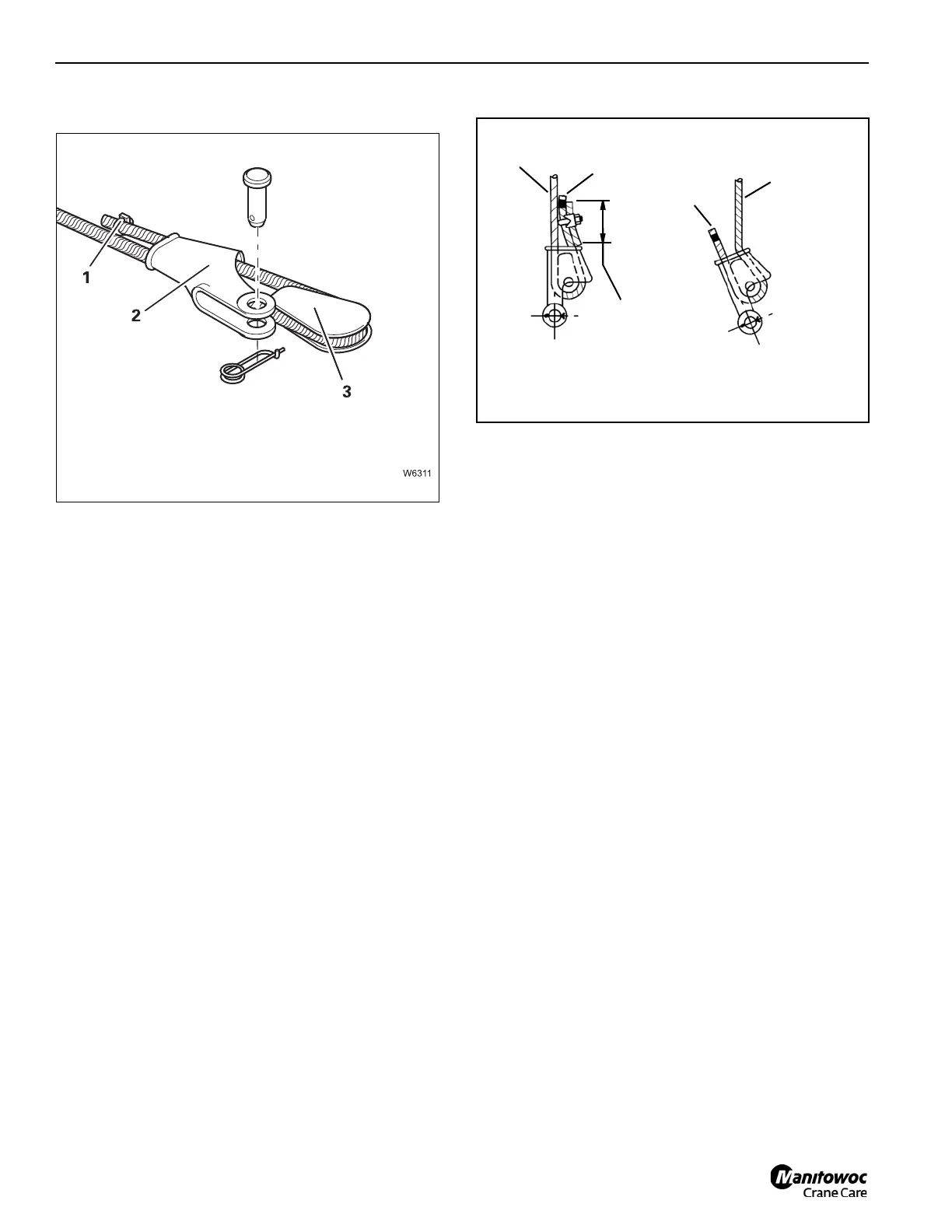
Attaching the rope end clamp
• Insert the hoist rope and rope wedge (3) into the rope
end clamp (2).
• Secure the rope clamp (1) to the loose end of the rope.
The rope clamp provides additional safety and prevents the
hoist rope from slipping out of the rope end clamp.
• Pull the rope end taut until the hoist rope fits snugly in
the rope end clamp.
1. Inspect the wedge and socket. Remove any rough
edges and burrs.
2. The end of the wire rope should be seized using soft, or
annealed wire or strand. If the end of the rope is welded,
the welded end should be cut off. Do not weld on size
6X37 rope. This will allow the distortion of the rope
strands, caused by the bend around the wedge, to
adjust themselves at the end of the line. Refer to
SECTION 1 - INTRODUCTION in the Service Manual
for wire rope procedures.
3. Make sure the live-end (Figure 6-51) of the rope is
directly in line with the ears of the socket and the
direction of pull to which the rope will be subjected. If the
rope is loaded into the socket incorrectly, under a load
the rope will bend as it leaves the socket, and the edge
of the socket will wear into the rope causing damage to
the rope and eventual failure.
.
4. Insert the end of the wire rope into the socket, form a
loop in the rope, and route the rope back through the
socket allowing the dead-end (Figure 6-51) to protrude
from the socket. Ensure the dead-end of the rope is of
sufficient length to apply end treatment to the dead-end
after the wedge has been seated.
5. Insert the wedge into the loop and pull the live-end of the
rope until the wedge and rope are snug inside the
socket. It is recommended that the wedge be seated
inside the socket to properly secure the wire rope by
using the crane’s hoist to first apply a light load to the
live-end.
6. After final pin connections are made, increase the loads
gradually until the wedge is properly seated.
7. The wire rope and wedge must be properly secured
inside the socket before placing the crane into lifting
service. It is the wedge that secures the wire rope inside
the socket. The dead-end treatment is used to restrain
the wedge from becoming dislodged from the socket
should the rope suddenly become unloaded due to the
headache ball or hook block striking the ground, etc;
refer to Dead-end Rigging, below.
Dead-end Rigging
Sketches A through F (Figure 6-52) illustrate various ANSI
approved methods for treating the dead-ends of wire ropes
which exit a wedge socket assembly. While use of the loop-
back method is acceptable, care must be exercised to avoid
the loop becoming entangled with tree branches and other
components during crane transport and with the anti-two
block system and other components during use of the crane.
Of the methods shown below, Grove prefers that method A
or F be used, i.e., clipping a short piece of wire rope to the
dead-end or using a commercially available specialty wedge.
Typically, it is recommended that the tail length of the dead-
end should be a minimum of 6 rope diameters but not less
Dead
End
Dead
End
Live End is
Entering
Wrong Side
Live
End
20 x Cable Dia
Minimum
RIGHT
WRONG
FIGURE 6-51
Wedge Socket
 Loading...


