GROVE 6-59
TMS9000-2 OPERATOR MANUAL SET-UP AND INSTALLATION
Published 02-21-2019, Control # 611-05
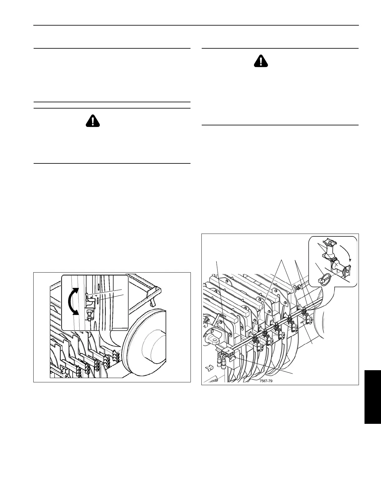
Holes (1) (Figure 6-116) are distributed on the inner wheel of
the hose drum. Rotating the latch (2) engages one of the
holes to lock the drum, preventing it from turning.
Unlocking the Drum
Rotate the latch (2) clockwise (A), to disengage it from the
hole.
Locking the Drum
1. Turn the hose drum until a hole is aligned with the latch
(2).
2. Rotate the latch (2) counterclockwise to position (B),
until the latch fully engages the hole.
Hydraulic Hose Installation
1. Unlock the hose drum.
2. Remove the hinged pins (1) (Figure 6-117) and fold up
the guide sheaves (2).
3. Remove the strain relief (3) from its main boom
mounting bracket (4) and pull the hydraulic hoses (5)
towards the boom nose.
4. Hook the strain relief onto the boom nose mounting
bracket (6).
5. Fold down the guide sheaves (2) and secure them with
the hinged pins (1).
Position for Main Boom Operation
The locking device on the hose drum must be undone:
CAUTION
Equipment Damage Hazard!
Always verify the drum is unlocked before using
extensions or other equipment that require hydraulic
power. Damage to hydraulic hoses or the boom may
occur.
CAUTION
Spring Loaded Equipment Hazard!
The drum must be locked before removal. The drum is
spring loaded and must be locked to prevent damage or
injury.
FIGURE 6-116
7567-34
1
2
B
A
1
CAUTION
Spring Loaded Equipment Hazard!
If the strain relief is detached after the locking device has
been released, do not under any circumstances let go of
the strain relief before it has been re-attached. If you let go
of the strain relief, the hydraulic hoses will spring back
uncontrollably due to the spring force in the hose drum
and may injure persons or damage parts of the crane.
 Loading...


