A - 4 VM600 networking manual MAVM600-NET/E
Edition 9 - February 2018
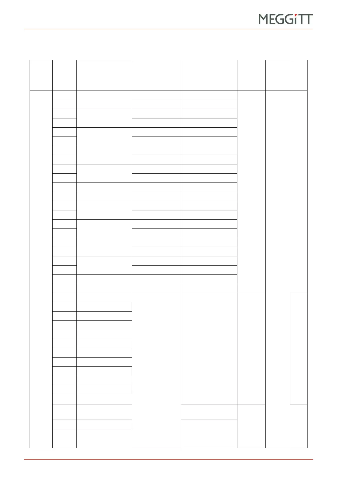
APPENDIX A: MPC4 MODBUS REGISTER DEFINITIONS
Table A-2: MPC4 register definitions
Read holding or input registers (Modbus function codes 03 and 04).
Rack
slot
number
(Snum)
Address
offset
(Aoff)
Channel
Internal value
type
Value
description
Modbus
starting
address
(MSA)
Value
Type
CPUM
<71
From
3 to 14
0
Channel 1, output 1
Value VAL
Unsigned
1 Configuration FSD
2
Channel 1, output 2
Value VAL
3 Configuration FSD
4
Channel 2, output 1
Value VAL
5 Configuration FSD
6
Channel 2, output 2
Value VAL
7 Configuration FSD
8
Channel 3, output 1
Value VAL
9 Configuration FSD
10
Channel 3, output 2
Value VAL
11 Configuration FSD
12
Channel 4, output 1
Value VAL
13 Configuration FSD
14
Channel 4, output 2
Value VAL
15 Configuration FSD
16
Dual-channel 1 and 2,
output 1
Value VAL
17 Configuration FSD
18
Dual-channel 3 and 4,
output 1
Value VAL
19 Configuration FSD
20 Speed 1 Value VAL
21 Speed 2 Value FSD
1000 Channel 1, output 1
Value
Alarm Status
(see Table 8-6 and
Table 9-10)
1001 Channel 1, output 2
1002 Channel 2, output 1
1003 Channel 2, output 2
1004 Channel 3, output 1
1005 Channel 3, output 2
1006 Channel 4, output 1
1007 Channel 4, output 2
1008 Dual-channel 1 and 2
1009 Dual-channel 3 and 4
1010 Speed 1
1011 Speed 2
1144
Basic and advanced
function
Logic Result
1145 Board status #1 Board Status
(see Table 9-12,
Table 9-13 and
Table 9-14)
1146 Board status #2
( ( slot − 3 ) * 22 ) + Aoff
( ( slot − 3 ) * 12 ) + Aoff
Only bits b0 to b6 are available
( ( slot − 3 ) * 3)
+ Aoff
 Loading...


