After selecting the panel function Sync.Sens.Level the contrast of the
inserted material (placed in the photoelectric sensor area) is shown on the
printer display. The left level value is the currently measured sensor
value
For all different contrast zones of the current material now sensor
values (level values in %) have to be measured. Place every specific zone
of the material in the photoelectric sensor area and read the level values.
Example: Self-adhesive material with black bars across the label
Zone of the inserted material: Sensor
measured value (level):
Label + liner + black bar 75 %
Label + liner 44 %
Liner (other names: carrier or backing) 12 %
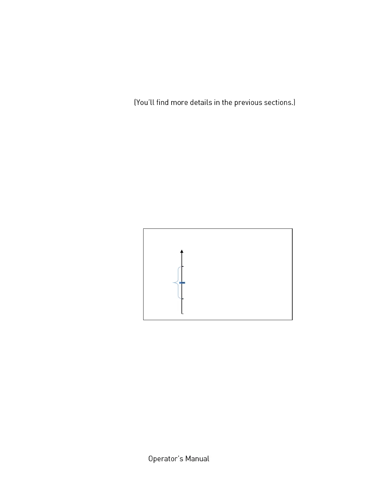
Calculation of the Switching Threshold
The middle between the label level (incl. liner) and the liner level has
to be calculated:
(44% - 12%)/2 + 12% = 28%
In this example the switching threshold is to be set to the value 28 %.
This setting value of 28 % is valid for printers with a threshold setting
range from 0 to 100%. If your printer is provided with a threshold setting
range from 0 to 200%, the setting value has to be doubled (here to 56 %).
The steps to set the Sync sensor level at the printer panel can be found on
the following page: