Structure and Assembly/Disassembly 7-15
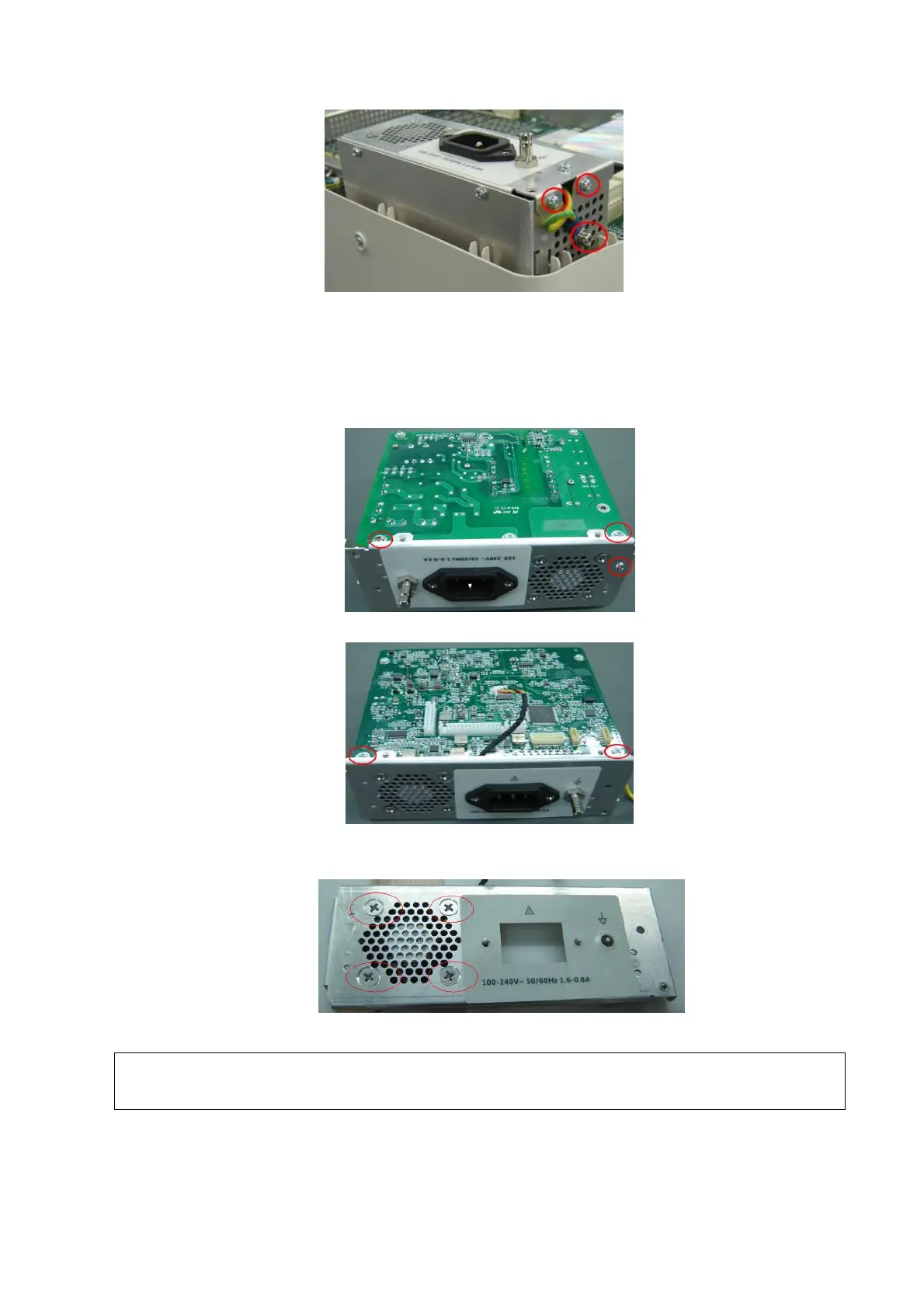
Figure 7-9 Disassemble the Power Module Assembly (2)
7.4.2.1 Power module Fan
1. Removing panhead screws with washers (5 M3X6) fixed on the power module assembly and
pulling out the plug of the fan connecting cables and power input outlet connecting cables,
you can take off the rear panel of power supply assembly.
Figure 7-10 Disassemble the rear panel of power supply assembly (1)
Figure 7-11 Disassemble the rear panel of power supply assembly (2)
2. Remove the 4 screws fixed on the fan and then take out the fan on the rear board.
Figure 7-12 Disassemble the Power Module Fan
7.4.2.2 DC-DC Power Board
1. Remove panhead screws with washers M3X6 (4) used to fix the DC_DC power board.
During the assembly, fan label must be pasted towards the surface of the machine,
and don’t confuse with fans of other products.

 Loading...


