7-28 Structure and Assembly/Disassembly
Figure 7-46 Disassemble the Monitor Assembly (2)
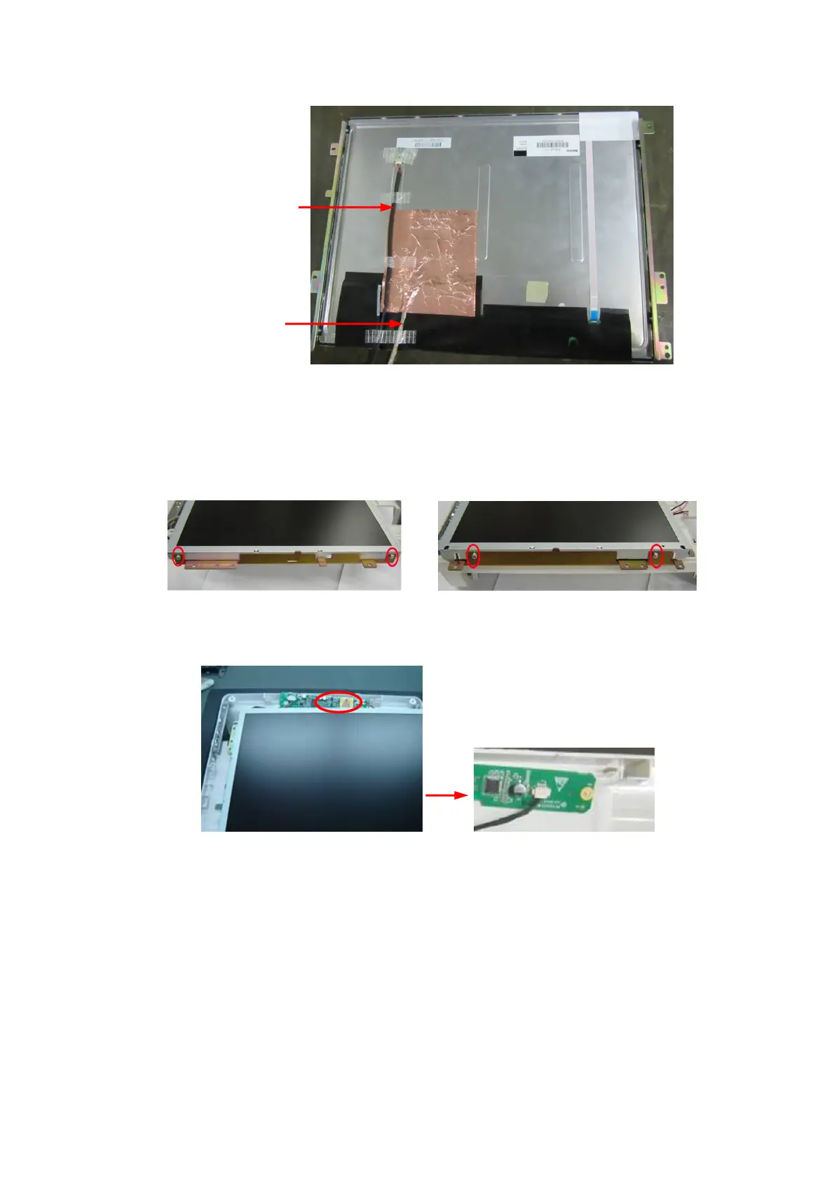
3. Split slowly copper paper used to paste LCD signal cable at the back of the LCD screen, and
pull out LCD signal cable.
4. After removing combination screws M3X4 (each for 2) used to fix the supporting assembly of
display on the left and right, you can pull out the LCD screen.
Figure 7-47 Disassemble the Monitor Assembly (3)
5. When installing, please attach the plug of backlight extension cables to the inverter board
socket.
Figure 7-48 View of Connecting backlight Extension Cable and Inverter Board

 Loading...


