Structure and Assembly/Disassembly 7-27
Figure 7-43 View of the Front Cover of the Display (2)
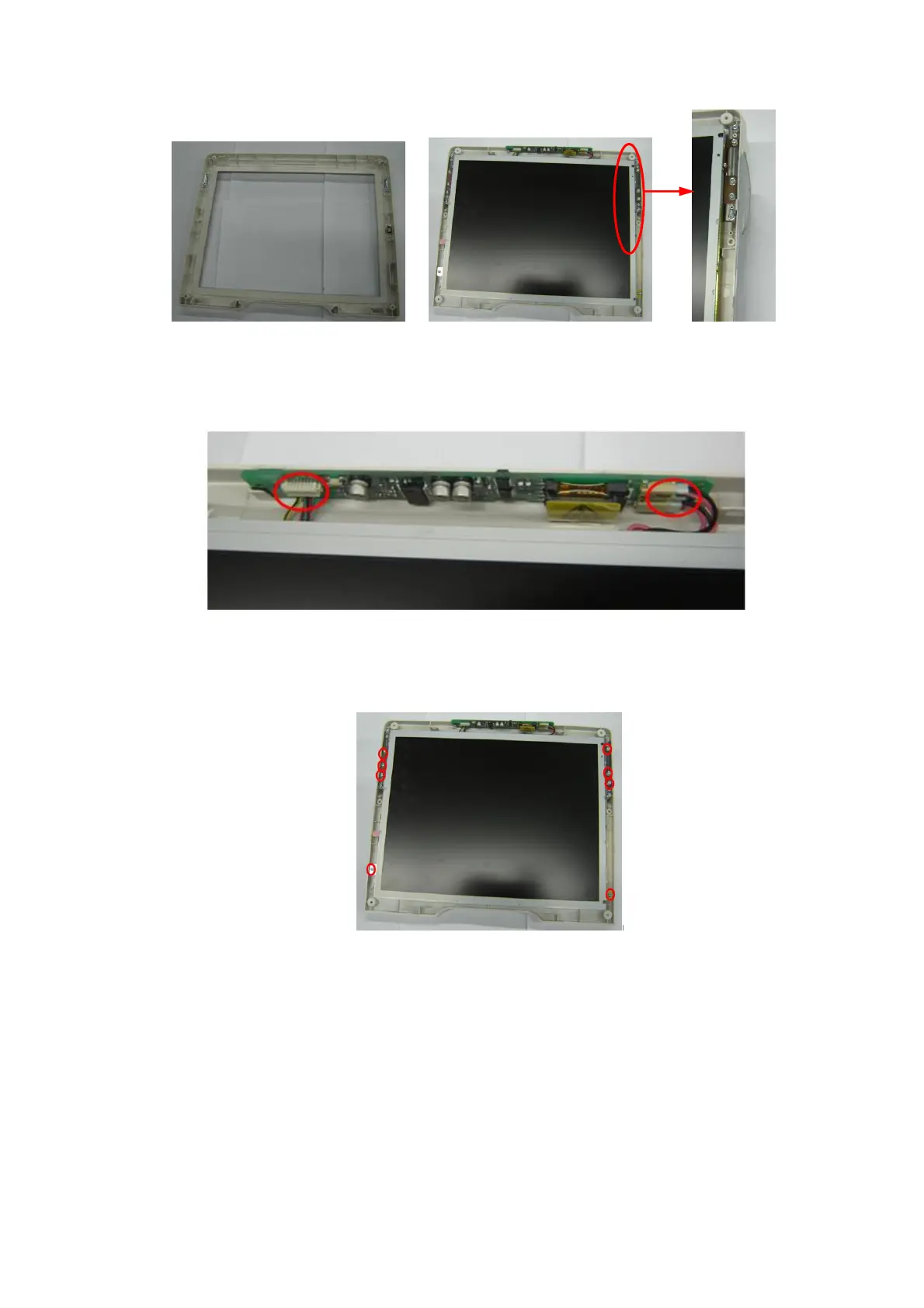
3. After pulling out inverter board a few from the bulges of the rear cover, and removing
connecting cables of the inverter board and backlight extension cables from the inverter
board, you could take out the inverter board.
Figure 7-44 Disassemble the Backlight Inverter Board of Display
7.4.7.2 LCD Screen
1. Remove combination screws (4 M3X8) used to be fastened the LCD screen.
Figure 7-45 Disassemble the LCD Screen (1)
2. Remove EEPOM connecting cable;

 Loading...


