About SMB Controller
5.
Insert the corresponding wiring adapters into the WA1, WA2, WA3, and WA4 sockets. See the
imprint on the adapters for orientation.
6.
Insert the DSP modules into the DSP Slot on the mainboard by replacing the fastening screw
with the standoff supplied with the module.
7.
Align the DSP module into the DSP slot and press down evenly on both connectors until they
stop.
Note:
A maximum of three DSP modules can be stacked. At least one DSP module is
required in addition to the onboard DSP.
8.
Repeat steps 6 -7 for all DSP modules and then secure the final module with the fastening
screw.
A maximum of three DSP cards can be stacked.
9.
Attach the cover.
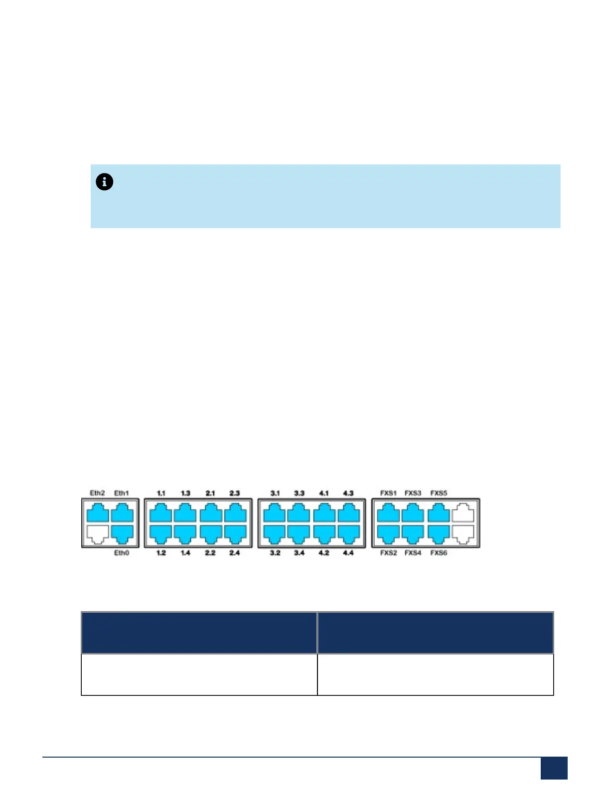
2.4.3.5 FXS terminal interfaces
The six FXS terminal interfaces of the mainboard are permanently routed to the front panel and
labelled accordingly. The two remaining RJ45 sockets, which are not labelled, empty and cannot
be used. With the appropriate interface cards and wiring adapters, additional FXS terminal
interfaces can also be made available at the RJ45 sockets 1.x. 4.x. The possible RJ45 sockets
are highlighted in color in the following figure.
Figure 12: Connection possibilities for FXS terminal interfaces
2.4.3.5.1 FXS interfaces
Feature MiVoice Business on SMB Controller
Pulse Dialing No
Document Version 1.0
System Manual for Mitel SMB Controller 40
 Loading...