What to do if Mitsubishi Electric Robotics shows error L3780?
- CchristinacarterSep 23, 2025
If Mitsubishi Electric Robotics displays error L3780, it indicates an invalid MELFA Smart Plus. Check the MELFA Smart Plus card or parameter.

What to do if Mitsubishi Electric Robotics shows error L3780?
If Mitsubishi Electric Robotics displays error L3780, it indicates an invalid MELFA Smart Plus. Check the MELFA Smart Plus card or parameter.
What to do if Mitsubishi Electric Robotics shows error L3781?
If Mitsubishi Electric Robotics displays error L3781, it indicates an invalid MELFA Smart Plus. Check the MELFA Smart Plus card or parameter.
What to do if Mitsubishi Electric Controller displays error H.6640 (Illegal parameter PMRSTDEC)?
If the Mitsubishi Electric Controller displays error H.6640 (Illegal parameter PMRSTDEC), it means that the parameter setting is illegal. Correct the parameter to resolve the issue.
What to do if the Mitsubishi Electric CR800-D shows error C.713n?
If the Mitsubishi Electric Controller displays error C.713n, it indicates that the timing belt consumption degree has exceeded the warning level. Replace the timing belt and reset the consumption degree.
What to do if Mitsubishi Electric CR800-D Controller displays error H.6640 (Illegal parameter PMSIGMNT)?
If your Mitsubishi Electric Controller shows error H.6640 (Illegal parameter PMSIGMNT), it means the parameter setting is illegal. Correct the parameter to resolve the issue.
What to do if Mitsubishi Electric CR800-D Controller displays error H.6640 (Illegal parameter PMSIGOH)?
If the Mitsubishi Electric Controller displays error H.6640 (Illegal parameter PMSIGOH), it means that the parameter setting is illegal. To fix this, correct the parameter.
What to do if Mitsubishi Electric Controller displays error H.6640 (Illegal parameter PMSIGGRS)?
If the Mitsubishi Electric Controller displays error H.6640 (Illegal parameter PMSIGGRS), it means the parameter setting is illegal. The suggested solution is to correct the parameter.
What to do if Mitsubishi Electric CR800-D Controller displays error H.6640 (Illegal parameter PMSIGBLT)?
If the Mitsubishi Electric Controller displays error H.6640 (Illegal parameter PMSIGBLT), it indicates the parameter setting is illegal. You should correct the parameter.
What to do if Mitsubishi Electric CR800-D displays error H.6640 (Illegal parameter PMSIGDEC)?
If the Mitsubishi Electric Controller displays error H.6640 (Illegal parameter PMSIGDEC), it means the parameter setting is illegal. You should correct the parameter.
What to do if Mitsubishi Electric CR800-D displays error H.6640 (Illegal parameter PMSIGBRG)?
If the Mitsubishi Electric Controller displays error H.6640 (Illegal parameter PMSIGBRG), the parameter setting is illegal. Correct the parameter to resolve the problem.
| Category | Controller |
|---|---|
| Protection Class | IP20 |
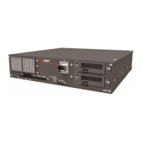
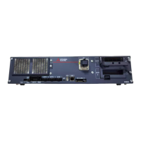
| Series | CR800-D |
| Type | Robot Controller |
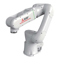
| Compatible Robots | Mitsubishi Electric Robots (MELFA) |
| Communication Interfaces | Ethernet, USB, Serial (RS-232) |
| Safety Features | Emergency stop |
| Operating Temperature | 0°C to 45°C (32°F to 113°F) |
| Storage Temperature | -20 to 70 °C |
Essential safety guidelines for robot operation and maintenance, covering training, work plans, and emergency stops.
Precautions regarding robot environment, transportation, installation, cabling, load limits, and operation state indication.
Safety measures for modifications, manual handling, power control, and SSCNET III cable usage.
Safety regarding wiring, network equipment suitability, and unauthorized network access.
List of revisions for the instruction manual, including revision date and details.
Explanation of warning symbols (Danger, Warning, Caution) used within the manual.
Details on the structure, compatible products, and related manuals of this instruction manual.
List of robot arms, controllers, software, and expansion cards compatible with the predictive maintenance function.
List of other manuals related to the predictive maintenance function and robot operation.
Overview of daily and periodic inspection types, including their frequencies and operating time thresholds.
Procedure and symptoms for inspecting and replacing the robot's timing belt, emphasizing tension adjustment.
Details on grease usage for reduction gears, lubrication intervals, and the necessity of periodic replacement.
Procedure for replacing the backup battery, essential for position detector data retention.
Definition and recommendation for robot overhaul, typically performed based on servo-on time to maintain performance.
Explanation of the predictive maintenance function's three core components: simulation, consumption degree calculation, and abnormality detection.
Estimates parts replacement and recommended maintenance times based on robot program patterns and simulations.
Calculates component consumption based on operating status, aiding maintenance timing and priority decisions.
Early detection of abnormalities in reduction gears or encoders without external sensors or PCs.
Estimates time to grease replenishment, timing belt replacement, and overhaul for key parts.
Explains '1 Cycle operation' and 'Program operation' methods for estimating maintenance times.
Details on confirming consumption degree, remaining time, operating information, and status via RT ToolBox3 screens.
Methods to check predictive maintenance data using RT ToolBox3 screens, parameters, and status variables.
Configuration steps for notification settings, detection levels, and operational items like maintenance reset.
Identifies target parts for abnormality detection: reduction gear, encoder data, encoder communication, and battery.
Details on viewing abnormality scores, log data, and detection status for each target part.
Methods to check abnormality detection data using RT ToolBox3 screens, parameters, and status variables.
Configuration of notification settings, level settings, and operational resets for abnormality detection.
Using Maintenance Simulation to estimate part replacement times and plan maintenance schedules when starting a system.
Checking consumption degree and abnormalities during periodic inspections for maintenance planning.
Responding to part consumption notifications to prevent production line stops and reduce downtime.
Acting on detected abnormalities to prevent failures, reduce downtime, and perform necessary maintenance.
Detailed steps for installing the MELFA Smart Plus Card into the robot controller and setting parameters.
Configuration of how to notify when consumption or abnormality is detected, including detection levels.
Procedure to set the function code and parameters for MELFA Smart Plus card for maintenance simulation in RT ToolBox3.
Procedure to restart the robot controller after enabling the predictive maintenance function.
Verification steps to confirm that the predictive maintenance function is enabled via LED status or RT ToolBox3 project tree.
Configuring notification methods for consumption and abnormality detection, including warning occurrence and signal output.
Setting detection levels for reduction gear, encoder data, and encoder communication scores for abnormality detection.
Method to set detection levels for reduction gear abnormality, considering score variation and operating conditions.
Illustrates setting detection levels based on log data, typically 10 points higher than the maximum observed score.
A case study showing how a reduction gear failure was detected by exceeding the set detection level.
Explanation of how encoder data or communication errors are scored and how to set detection levels for these abnormalities.
Instructions on how to start and use the real-time monitor oscillograph in RT ToolBox3 to check fault detection scores.
Overview of the Predictive Maintenance Signal screen where signal numbers are assigned to parameters.
Procedure for setting axis bit patterns for reset/pause using the IODATA Setting screen.
Procedure to retrieve the function code of the MELFA Smart Plus Card from the robot controller.
Setting the PMENA parameter to enable the predictive maintenance function for maintenance simulation.
The hierarchical menu structure in RT ToolBox3 for accessing various predictive maintenance functions.
The main screen displaying overall status of reduction gear, encoder, battery, and total evaluation results.
Screen displaying consumption degrees of maintenance and overhaul parts for each joint axis.
Screen displaying scores for reduction gear and encoder calculated by the abnormality detection function.
Area showing total scores for maintenance and overhaul parts, including consumption degrees and remaining time.
Area displaying score status, normal/fault status of reduction gear, encoder, and battery.
Display area for messages related to consumption status or abnormality detection, guiding maintenance actions.
Classification of parts into maintenance (grease, timing belt) and overhaul (reduction gear, bearing, etc.) for consumption degree calculation.
Graphical and numerical display of consumption degree for each part and joint axis, based on recommended maintenance time.
Display of messages indicating part status and guiding necessary measures when remaining time is low or score exceeds levels.
Indicates the current score for each joint axis related to reduction gear, encoder data, and encoder communication.
Displays historical log data of maximum scores for each joint axis over the past 365 days, with color-coded status.
Displays messages when abnormalities are detected, guiding users on content and necessary measures.
Details of integration time and accumulation count data that can be managed and displayed, reset after overhaul.
Estimates years until grease replenishment, timing belt replacement, and overhaul for key robot components.
Explains '1 Cycle operation' and 'Program operation' as methods for estimating maintenance times.
Note on using Maintenance Simulation in RT ToolBox3, requiring MELFA Smart Plus card function code and parameter settings.
Guidelines for 1 Cycle operation, including handling signal waits, avoiding infinite loops, and including all necessary instructions.
Ensuring the robot is at the correct starting position for accurate 1 Cycle operation calculation.
Steps to open the Maintenance Simulation screen within RT ToolBox3 by navigating the project tree.
Selecting the '1 Cycle' option on the Maintenance Simulation screen to initiate the cycle-based estimation.
Choosing the specific robot program to be analyzed for maintenance simulation from the 'Select Robot Program' screen.
Defining the start and end lines of the robot program for accurate 1 Cycle operation analysis.
Execution of the selected robot program for maintenance simulation, with status updates on the operation panel.
Display of simulation results showing years until replacement/overhaul for different parts and axes, based on operation time.
Option to update the simulation results graph by changing 'Operation Time of a Day' and 'Working Days in a Month'.
Automatically running the robot program that performs maintenance simulation.
Accessing the Maintenance Simulation screen via the RT ToolBox3 project tree.
Selecting the 'Program' option on the Maintenance Simulation screen for program-based estimation.
Initiating the maintenance simulation by clicking the 'Start' button on the Maintenance Simulation screen.
Ending the maintenance simulation by clicking the 'End' button, which displays the results screen.
Displaying simulation results after completing 'Start' and 'End' operations, based on updated conditions.
Details of error numbers, messages, and recommended measures for consumption degree issues of maintenance parts like grease and timing belts.
Information on consumption degree for grease and timing belts, including error codes, messages, and recommended actions.
Details on consumption degree for overhaul parts (reduction gear, bearing, ball screw), including error codes and recommended overhaul actions.
Information on servo ON time exceeding overhaul periods, with error codes and recommended overhaul procedures.
Details on abnormality detection for reduction gear and encoder, including error numbers, messages, and recommended measures.
Information on reduction gear abnormality detection, including error codes, messages, and recommended inspection/replacement actions.
Details on encoder data and communication abnormality detection, including error codes, messages, and recommended actions.
Information on battery voltage status, including error codes for low voltage or outage, and replacement recommendations.
Displays and allows pausing of warning occurrences and signal outputs for consumption degree and abnormality detection.
Resets accumulated data for consumption degree and abnormality detection scores after maintenance tasks like part replacement.
Procedures for backing up and restoring predictive maintenance information to migrate data between controllers or after component replacement.
Detailed steps for creating a backup file for predictive maintenance information, including selecting a backup folder.
Procedure to transfer backed-up predictive maintenance information from a personal computer back to the robot controller.
Selecting specific parts (Grease, Timing Belt, etc.) for which maintenance logs are to be displayed.
Displays the components selected in the 'Select Parts' field, with a maximum of 10 log items per axis.
Details of data recorded in the maintenance log after resets, including date, time, consumption degree, and accumulation count.
Overview of using MelfaRXM.ocx or SLMP protocols to collectively manage maintenance information across an entire production line.
Table detailing output data for basic information, consumption degree, remaining time, consumption status, and notification pause status.
Continuation of output data details, covering maintenance log, score, abnormality detection status, notification methods, and detection levels.
Returns the serial number of the robot body.
Variables related to operating information: Power ON time, Servo ON time, Operation time, Actual operation time, Servo ON count, Motor rotation count.
Variables related to the maintenance log for various parts like grease, timing belt, reduction gear, bearing, ball screw, and overhaul.
Variables related to consumption degree: overall and part-specific degrees for maintenance and overhaul parts, and remaining time.
Variables indicating consumption status (normal, warning, low) for maintenance and overhaul parts.
Variables related to notification pause status for various parts and servo ON time.
Variables for abnormality detection log data: count, reduction gear, encoder data, and encoder communication logs.
Variables representing the score for reduction gear, encoder data, and encoder communication abnormalities.
Variables indicating the abnormality detection status for reduction gear, encoder data, encoder communication, and battery voltage.
Variables for detection level settings for reduction gear, encoder data, and encoder communication abnormality detection.
Variables related to the MELFA Smart Plus card, indicating function usage status and name.
Returns the serial number of the robot body.
Returns the serial number of the robot controller.
Returns the cumulative time of power supply ON of the robot controller since the last overhaul.
Returns the cumulative time of servo ON of the robot body since the last overhaul.
Returns the cumulative time of the robot controller's operation from the last overhaul.
Returns the cumulative moving time of the robot body from the last overhaul.
Returns the cumulative count of servo ON of the robot body from the last overhaul.
Returns the cumulative number of rotations of the motor of the robot body for a specified axis.
Returns the maintenance count (reset count) of the grease for a specified axis.
Returns the maintenance count (reset count) of the timing belt for a specified axis.
Returns the maintenance count (reset count) of the decelerator for a specified axis.
Returns the maintenance count (reset count) of the bearing for a specified axis.
Returns the maintenance count (reset count) of the ball screw/ball spline for a specified axis.
Returns the maintenance count (reset count) of the overhaul based on servo ON time.
Returns maintenance log data (date, time, consumption degree) for grease.
Returns maintenance log data (date, time, consumption degree) for timing belt.
Returns maintenance log data (date, time, consumption degree) for reduction gear.
Returns maintenance log data (date, time, consumption degree) for bearing.
Returns maintenance log data (date, time, consumption degree) for ball screw/ball spline.
Returns maintenance log data (date, time, servo ON time) for overhaul.
Returns the overall consumption degree of maintenance parts (grease and timing belt).
Returns the overall consumption degree of overhaul parts (decelerator, bearing, ball screw, ball spline).
Returns the consumption degree of grease for a specified axis.
Returns the consumption degree of the timing belt for a specified axis.
Returns the consumption degree of the decelerator for a specified axis.
Returns the consumption degree of the bearing for a specified axis.
Returns the consumption degree of the ball screw/ball spline for a specified axis.
Returns the consumption status of maintenance parts (grease, timing belt).
Returns the consumption status of overhaul parts (decelerator, bearing, ball screw, ball spline).
Returns the consumption status of grease for a specified axis.
Returns the consumption status of timing belt for a specified axis.
Returns the consumption status of decelerator for a specified axis.
Returns the consumption status of bearing for a specified axis.
Returns the consumption status of ball screw/ball spline for a specified axis.
Returns the arrival status to the specified overhaul time of servo ON time.
Returns the pause status of warning/signal output for grease consumption of a specified axis.
Returns the pause status of warning/signal output for timing belt consumption of a specified axis.
Returns the pause status of warning/signal output for reduction gear consumption of a specified axis.
Returns the pause status of warning/signal output for bearing consumption of a specified axis.
Returns the pause status of warning/signal output for ball screw/ball spline consumption of a specified axis.
Returns the pause status of warning/signal output for servo ON time.
Details about the abnormality detection log, including log data count and specific log data retrieval for reduction gear.
Retrieves abnormality detection log data and score for reduction gear for a specified axis and log number.
Retrieves abnormality detection log data and score for encoder data abnormality for a specified axis and log number.
Retrieves abnormality detection log data and score for encoder communication abnormality for a specified axis and log number.
Returns the score of reduction gear abnormality detection for a specified axis.
Returns the score of encoder data abnormality detection for a specified axis.
Returns the score of encoder communication abnormality detection for a specified axis.
Returns the abnormality detection status for reduction gear of a specified axis.
Returns the abnormality detection status for encoder data abnormality of a specified axis.
Returns the abnormality detection status for encoder communication abnormality of a specified axis.
Returns the abnormality detection status of battery voltage.
Returns the pause status of warning/signal output for reduction gear abnormality detection.
Returns the pause status of warning/signal output for encoder data abnormality detection.
Returns the pause status of warning/signal output for encoder communication abnormality detection.
Returns the detection level for reduction gear abnormality detection of a specified axis.
Returns the detection level for encoder data abnormality detection of a specified axis.
Returns the detection level for encoder communication abnormality detection of a specified axis.
Common parameters for predictive maintenance functions, including pause method, enable/disable switching, and version management.
Parameters for setting warning remaining days, operation time of a day, and notification interval for part consumption.
Parameters for notification methods of maintenance and overhaul part consumption.
Parameters for acquiring integration time data: Power ON time, Servo ON time, Operation time, Actual operation time.
Parameters for acquiring accumulation count data: Servo ON count, Motor cumulative rotation count.
Parameters for acquiring consumption degree data for mechanism total (maintenance/overhaul parts).
Parameters for acquiring consumption degree for grease, timing belt, reduction gear, bearing, and ball screw/ball spline.
Parameters for acquiring consumption status for mechanism total (maintenance/overhaul parts) and individual parts.
Parameters for acquiring consumption status for servo ON time.
Parameters for resetting accumulated consumption degree data for grease, timing belt, reduction gear, bearing, and ball screw/ball spline.
Parameters for resetting overhaul and new robot consumption degree data.
Parameters for specifying pause of warning occurrence/signal output for grease and timing belt consumption.
Parameters for specifying pause of warning for reduction gear, bearing, ball screw/spline, and servo ON time.
Parameter to specify data for retrieving maintenance logs, including log number and joint axis number.
Parameter to get maintenance log data for grease, including log number, axis, date, time, and consumption degree.
Parameters to get maintenance log data for timing belt, reduction gear, bearing, and ball screw/ball spline.
Parameters for setting detection levels for reduction gear, encoder data, and encoder communication abnormalities.
Parameters for setting abnormality detection status for reduction gear, encoder data, and encoder communication.
Parameter for abnormality detection status of battery voltage.
Parameter to reset maximum score values for encoder data and communication abnormalities.
Parameter to specify pause of warning for reduction gear abnormality detection.
Parameters to specify pause of warning for encoder data abnormality detection.
Parameter to specify data for retrieving abnormality detection logs, including log number.
Parameter to get abnormality detection log data for reduction gear, including log number, date, and scores for multiple axes.
Dedicated output signals for consumption degree warnings and input signals for resetting consumption degree.
Output signals for maintenance warnings related to consumption of grease, timing belt, reduction gear, bearing, ball screw, and servo ON time.
Input signals for resetting consumption degree information for various parts and overhaul/new robot scenarios.
Input signals for pausing warning occurrence/signal output for consumption of grease, timing belt, reduction gear, bearing, ball screw/spline, and servo ON time.
Output signals for maintenance warnings related to abnormality detection (reduction gear, encoder data, communication).
Input signal for resetting abnormality detection status information for the encoder.
Input signals for pausing warning occurrence/signal output for reduction gear, encoder data, and communication abnormality detection.
List of error numbers related to the predictive maintenance function, their causes, and countermeasures.
Troubleshooting for common errors like robot arm serial number mismatch, backup mismatch, and version mismatch.
Error numbers related to consumption degree calculation, including grease, timing belt, and overhaul periods.
Error numbers related to illegal parameters for various signal and reset functions.
Error numbers for illegal parameters of pause functions and battery status errors.
Errors related to abnormality detection, including score exceeding detection levels and illegal parameter settings.
Error numbers for illegal parameters and battery status errors (no battery, low battery).
Error numbers related to the MELFA Smart Plus card, including invalid card and multiple card installation issues.


