3
SPECIFICATIONS
3.2 Function List
3.2.3 Input signal error detection function
3 - 22
1
OVERVIEW
2
SYSTEM
CONFIGURATION
3
SPECIFICATIONS
4
SETUP AND
PROCEDURES
BEFORE OPERATION
5
UTILITY PACKAGE
(GX CONFIGURATOR-
AD)
6
PROGRAMMING
7
ONLINE MODULE
CHANGE
8
TROUBLESHOOTING
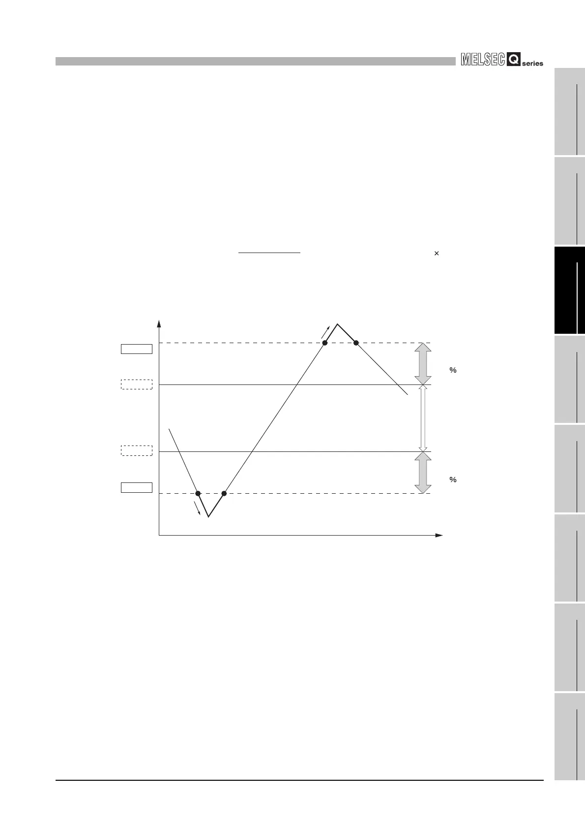
(8)Setting example of input signal error detection
Apply the following values to the calculation formula for an input signal error detection
lower limit value.
• Input signal error detection lower limit value: 2.4mA
• Lower limit value of the input range (offset value): 4.0mA
• Gain value: 20.0mA
Therefore, Set 100 (10.0%) as an input signal error detection setting value.
The input signal error detection values act as follows in this case. (Because of the set-
ting value of 100 (10%), an error is detected not only at 2.4mA but also at 21.6mA.)
Example) To detect an input signal error when the analog input value falls below
2.4mA in the channel where the input range of 4 to 20mA (extended
mode) and the normal resolution mode is set
=
Input signal error detection
setting value
Input signal error detection
upper limit value
-
Lower limit value of each
range
Gain value of each range - Offset value of each range
1000
Input signal error detection
upper limit value
21.6mA
Offset value
20mA
Gain value
4mA
Input signal error detection
lower limit value
Error
Error
1.6mA
(10.0 of 1.6mA)
1.6mA
(10.0 of 1.6mA)
16mA
(Gain value - Offset value)
2.4mA
 Loading...


