6 Wiring of the Device
42 Rev. 03/2019
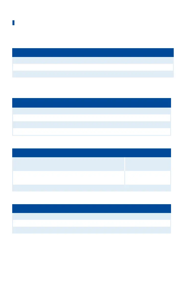
One revolution of the pickup changes the distance as follows:
Thread Change in distance
M12x1 1 revolution ≙ 1 mm (0.04'')
5/8"-18 UNF 1 revolution ≙ 1.41 mm (0.05")
3/4"-16 UNF 1 revolution ≙ 1.59 mm (0.06")
Allocation of the Wire Colors (Example Configuration)
Camshaft
PIN Designation Wire color
1 Pickup 1 Power Brown
2 Pickup 1 Signal black
3 Pickup 1 GND blue
4 Pickup 1 Shield Shield
Crankshaft (Reset)
PIN Designation Wire color
6 Pickup 2 Signal Flywheel with pin
White
Flywheel with hole
Brown
7 Pickup 2 GND Flywheel with pin
Brown
Flywheel with hole
White
8 Pickup 2 Shield Shield
Crankshaft
PIN Designation Wire color
10 Pickup 3 Signal White
11 Pickup 3 GND Brown
12 Pickup 3 Shield Shield
For problems with the pickup signals, refer to the section Pickup Input Errors on page 164.