6 Wiring of the Device
Rev. 03/2019 49
5. From the PowerView3 power supply cable, plug the L– wire (white) into contact . For
plugging into the contact, use a wire end ferrule provided with the PowerView3.
6. From the PowerView3 power supply cable, plug the L+ wire (brown) into contact
. For
plugging into the contact, use a wire end ferrule provided with the PowerView3.
7. Insert the connector provided with the PowerView3 into the power supply connection of the
ignition controller.
8. Insert the connector at the other end of the PowerView3 power supply cable into the
PowerView3 power supply connection.
9. Connect the device's power supply.
The power supply of the PowerView3 is now provided through the connector on the
ignition controller.
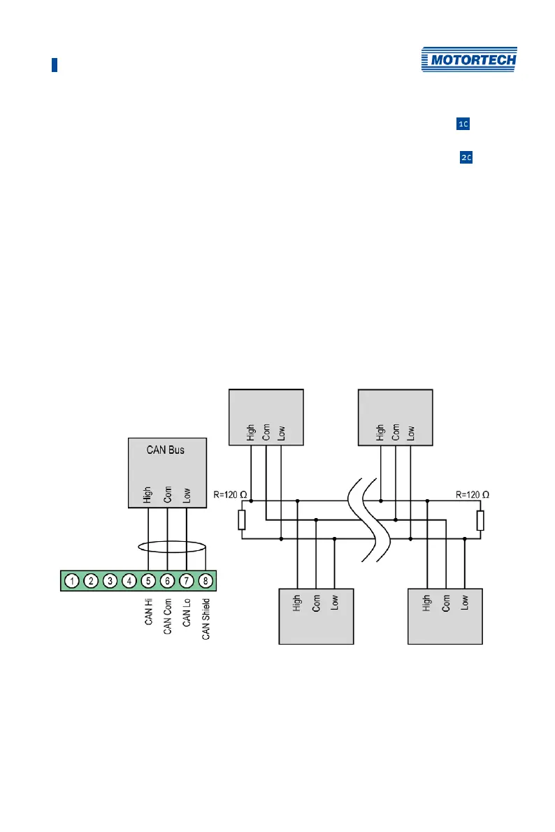
6.1.7 Output Wiring – CAN Bus Interface
The product must be connected to a CAN bus as follows:
First device Second-to-last device
Second device Last device
Notice: The CAN-Bus connectors 1-4 are currently unavailable.