6 Wiring of the Device
Rev. 03/2019 37
6.1.1 Input Wiring
For the standard MIC5 version, the connections for the input wiring are located on the connector
strip below the service cover (see LEDs and Connections on page 30). The wiring to the connector
strips is fed through the PG screw joints at the device front.
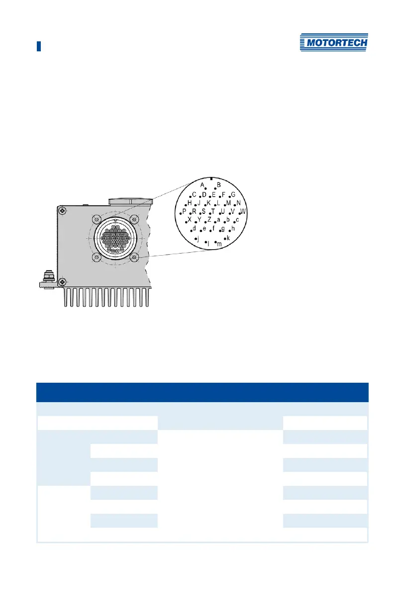
For device versions without a service cover, the input wiring is established using a 35-pole input
connector at the device front.
35-Pole Input Connector
35-pole input connector (outside view)
Assignment of the Connections
The table contains the connection assignment of different MIC5 versions. The wiring examples
contained in this operating manual refer to devices with a service cover and connector strip.
Pin designation Connection no. on connector strip 35-pole connector
L – (negative pole) Power 1 B
L + (24 V) 2 A
Pickup 1 Power Pickup 1 C
Signal 2 D
GND 3 E
Shield 4 F
Pickup 2 Power 5 G
Signal 6 H
GND 7 J
Shield 8 K